Downhole Rotational Vibrator

a vibrator and rotational technology, applied in the direction of manufacturing tools, sealing/packing, borehole/well accessories, etc., can solve problems such as jarring impacts

Active Publication Date: 2012-11-15
BAKER HUGHES INC
View PDF3 Cites 3 Cited by
  • Summary
  • Abstract
  • Description
  • Claims
  • Application Information

AI Technical Summary

Benefits of technology

[0005]The present invention provides a jarring device that can be run into a flowbore on a running string and used to remove a stuck tool. The jarring device can be affixed to the stuck tool and then actuated to create jarring impacts that are imparted to the stuck tool in order to remove it from the flowbore.

Problems solved by technology

Rotation of the impact rotator with respect to the housing creates jarring impacts which are transmitted through the housing to the stuck tool.

Method used


Image

  • Downhole Rotational Vibrator
  • Downhole Rotational Vibrator
  • Downhole Rotational Vibrator

Examples


Embodiment Construction

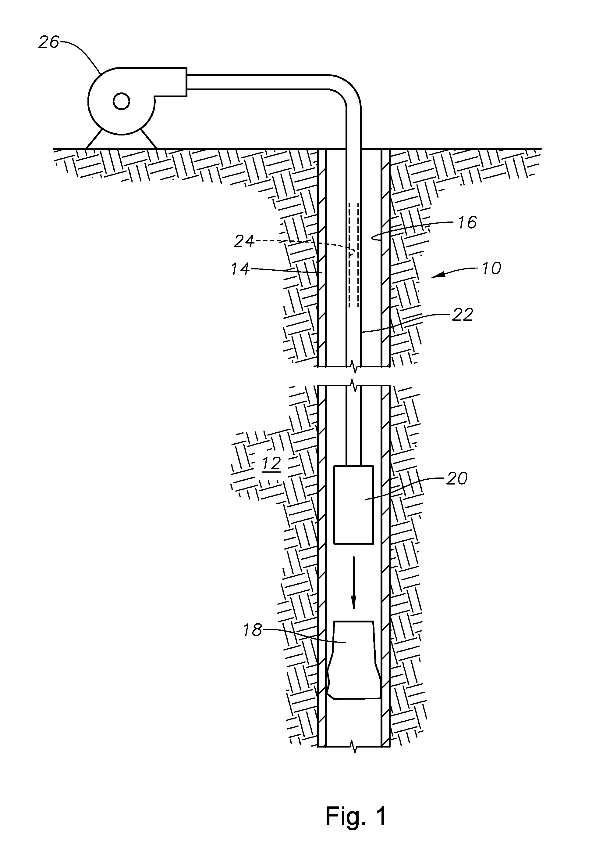
[0016]FIG. 1 depicts an exemplary wellbore 10 that has been drilled through the earth 12. The wellbore 10 is lined with casing 14 and defines a flowbore 16. The flowbore 16 contains a stuck tool 18 that must be removed by vibratory jarring. Although this example depicts the flowbore 16 which contains the stuck tool 18 as being defined by the wellbore casing 14, those of skill in the art will understand that the flowbore that contains a stuck tool might as well be defined within a concentric liner or within production tubing that is disposed within the casing 14.

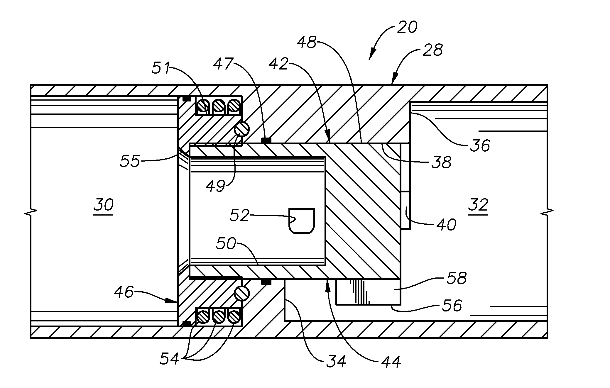
[0017]A rotational vibrator 20 constructed in accordance with the present invention is shown being run into the wellbore 10 on a running string 22. The running string 22 may be conventional end-to-end tubing string sections or coiled tubing, of a type known in the art. The running string 22 defines a central flow passage 24 through which fluid can be flowed. The vibrator 20 is removably secured to the stuck tool 18 by a latch...


PUM


Abstract

A jarring device includes an outer housing which defines an axial flow path therethrough. An impact rotator is retained within the housing and is rotatable therewithin between a first rotational position and a second rotational position to create a jarring impact. A torsional spring biases the impact rotator toward the first rotational position. Fluid flow through the housing rotates the impact rotator from the first to the second rotational position.

Description

BACKGROUND OF THE INVENTION[0001]1. Field of the Invention[0002]The invention relates generally to vibratory jarring devices used for removing devices from a flowbore.[0003]2. Description of the Related Art[0004]Jarring devices are used to remove objects from a flowbore. Typically, jarring devices are run into a flowbore and secured to a stuck device or object. Thereafter, the jarring device is actuated to generate jarring impacts which are delivered to the stuck device or object to free it from the flowbore. Jarring devices are described in U.S. Pat. No. 6,474,421, issued to Stoesz.SUMMARY OF THE INVENTION[0005]The present invention provides a jarring device that can be run into a flowbore on a running string and used to remove a stuck tool. The jarring device can be affixed to the stuck tool and then actuated to create jarring impacts that are imparted to the stuck tool in order to remove it from the flowbore.[0006]An exemplary jarring device is described which includes an outer h...

Claims


Application Information

Patent Timeline
Patent Type & Authority Applications(United States)
IPC IPC(8): E21B31/00
CPCE21B31/113E21B31/005
Inventor XU, RICHARD YINGQING
Owner BAKER HUGHES INC
Why Eureka
Try Eureka