Absolute Encoder and Rotary Position Data Transmission Method
An absolute encoder and rotary position technology, which is applied in the direction of converting sensor output, instruments, measuring devices, etc., can solve the problems of time-consuming, large number of pulses, etc., and achieve the effect of fast transmission
- Summary
- Abstract
- Description
- Claims
- Application Information
AI Technical Summary
Problems solved by technology
Method used
Image
Examples
Embodiment approach 1
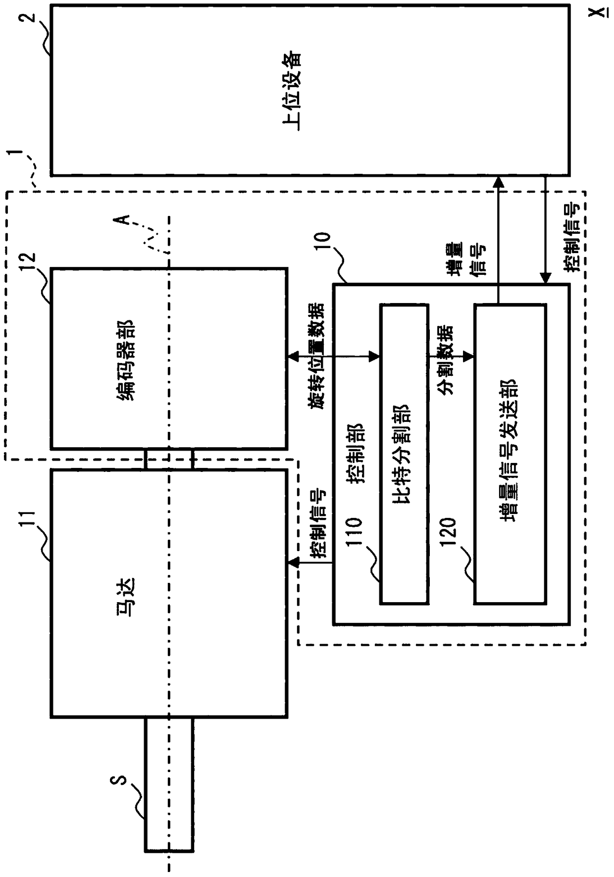
[0150] In addition to the above-described embodiment, each bit length of the divided data may be determined based on a parameter that can be set on the high-level device 2 side, that is, on the client side. Hereinafter, this structure will be described as another Embodiment 1. FIG.
[0151] according to Figure 4 (a) is described as a specific example: as a parameter indicating a predetermined bit length divided by the host device 2, a parameter table indicating a parameter number and a bit length of divided data is designated by the client and set in the control unit 10. middle. The control unit 10 stores this parameter table in advance, for example, as an internal parameter (client setting) in a built-in storage medium, and refers it when dividing the rotational position data. Alternatively, it may be transmitted from the host device 2 without being stored in the built-in storage medium. Here, the bit length of the divided data can be designated as a value from 0 to 24, f...
Embodiment approach 2
[0159] Furthermore, it is also possible to set a bit length exceeding the total number of bits of the rotation position data in the parameter table described in the first embodiment. Hereinafter, this structure will be described as another Embodiment 2. FIG.
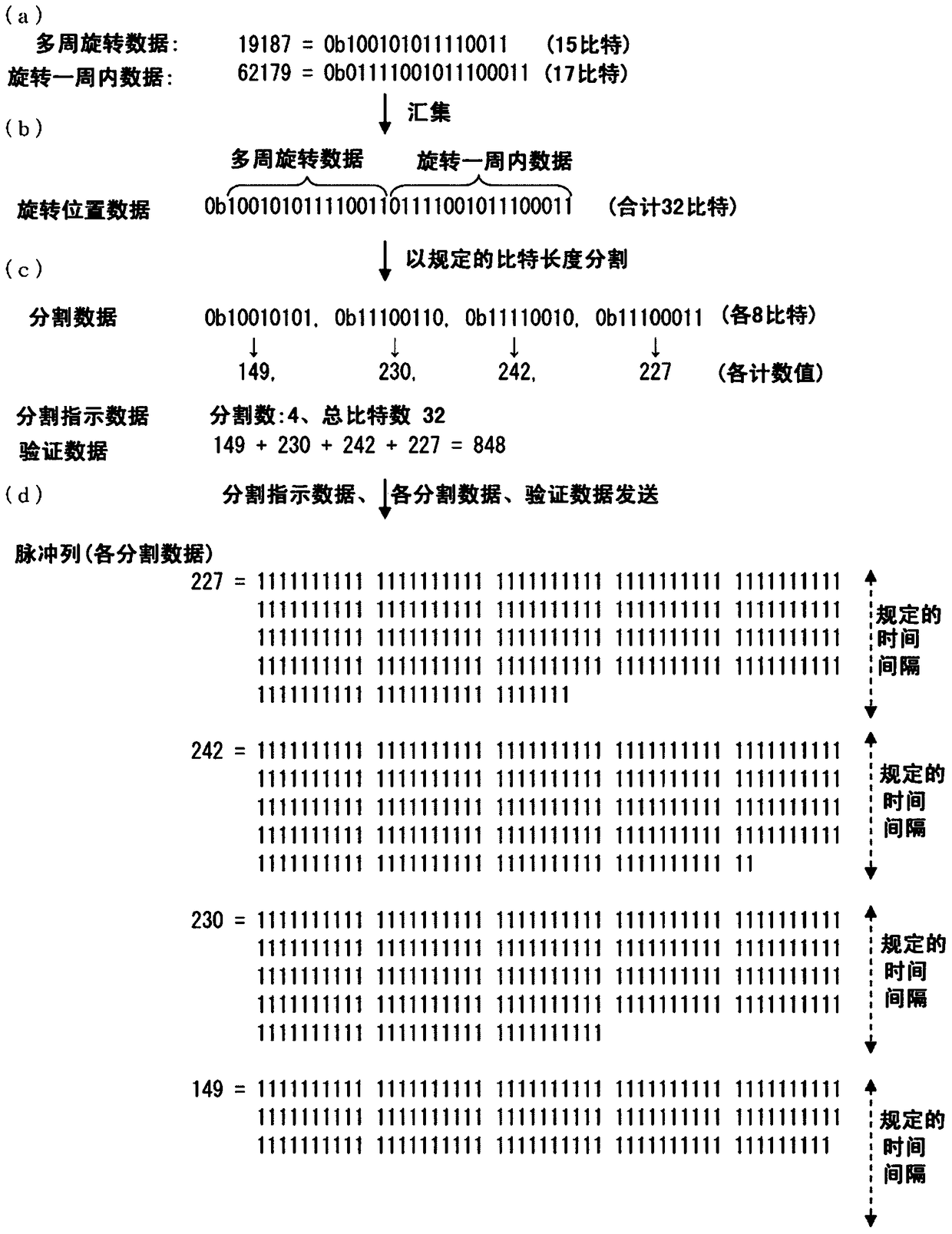
[0160] according to Figure 4 (b) As a specific example, the total number of bits of the rotation position data is 32 bits, corresponding to the parameter numbers "0", "1", "2", "3", "4", and "5" in the parameter table The case where the bit lengths of 1 are respectively set to "2", "8", "8", "8", "8", and "0" will be described as an example.
[0161] In this example, the control unit 10 assigns "0" for 2 bits to the part exceeding 32 bits, and can transmit the divided data of the parameter number 0 by making the host device 2 recognize that there is a transmission time of 2 bits. Thereafter, the control unit 10 transmits four divided data divided by 8 bits in the same manner as in the first embodiment described above....
PUM
 Abstract
Description
Claims
Application Information
 - R&D
- Intellectual Property
- Life Sciences
- Materials
- Tech Scout
- Unparalleled Data Quality
- Higher Quality Content
- 60% Fewer Hallucinations
Browse by: Latest US Patents, China's latest patents, Technical Efficacy Thesaurus, Application Domain, Technology Topic, Popular Technical Reports.
© 2025 PatSnap. All rights reserved.Legal|Privacy policy|Modern Slavery Act Transparency Statement|Sitemap|About US| Contact US: help@patsnap.com


