A motor control device that controls a motor based on the back EMF voltage of the motor winding

A technology of motor control and back electromotive force, applied in the direction of motor generator control, electromechanical transmission control, electronic commutation motor control, etc., can solve the problems of reducing productivity, correction amount error, phase lag, etc.

Active Publication Date: 2019-07-26
CANON KK
View PDF6 Cites 0 Cited by
  • Summary
  • Abstract
  • Description
  • Claims
  • Application Information

AI Technical Summary

Problems solved by technology

[0005] However, with the configuration disclosed in Japanese Patent No. 5170505, a phase lag caused by the low-pass filter occurs, and a lag occurs in the estimation of the rotational position and the rotational speed of the rotor
Due to this hysteresis, the responsiveness and stability of the control loop decreases
With the configuration disclosed in Japanese Patent No. 4154149, phase lag does not occur, but in order to obtain back EMF voltage data, measurement using a dedicated device needs to be performed in advance, which reduces productivity
With the configuration disclosed in Japanese Patent No. 4631672, the extracted harmonic components include those generated from counter-EMF voltage distortion and those that appear due to speed changes and load changes, and there is no distinction between these harmonic components , therefore, the error is included in the calculated correction for the rotational position
It is also difficult to eliminate the effect of the phase shift caused by the high-pass filter, and the error caused by the phase shift will also appear

Method used


Image

  • A motor control device that controls a motor based on the back EMF voltage of the motor winding
  • A motor control device that controls a motor based on the back EMF voltage of the motor winding
  • A motor control device that controls a motor based on the back EMF voltage of the motor winding

Examples


no. 1 example

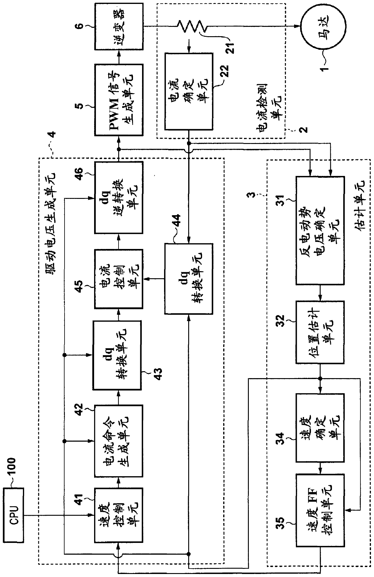
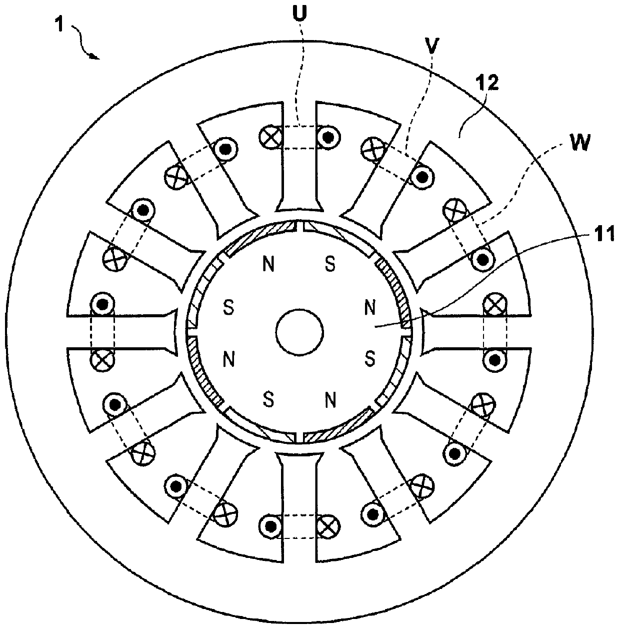
[0025] Hereinafter, the present embodiment will be described using a motor control device that controls a three-phase DC brushless motor having eight poles and twelve slots. Note that the motor controlled by the motor control device of the present invention is not limited to being a three-phase DC brushless motor with eight poles and twelve slots, and for example, the present invention can also be applied to other kinds of motors such as two-phase stepper motor. figure 2 The motor 1 of this embodiment is shown. Notice, figure 2 is a cross-sectional view of a plane perpendicular to the rotation axis of the motor. The rotor 11 includes eight poles (four pairs) of permanent magnets. The stator 12 has twelve teeth (slots) arranged in 30 degree increments, and the windings U, V and W are wound around the slots. Note that windings U, V and W are arranged on different slots.

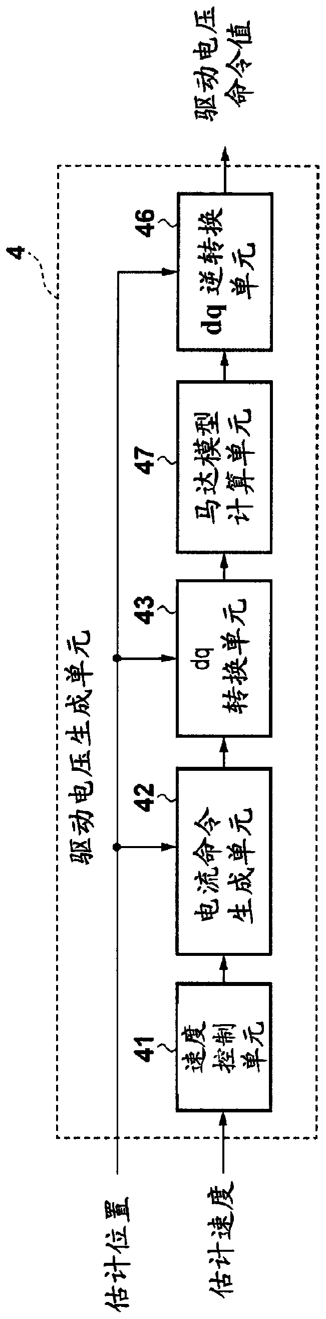
[0026] figure 1 is a diagram showing the overall configuration of the motor control device according...

no. 2 example

[0075] Next, a second embodiment having points of interest different from points of the first embodiment will be described. Figure 12 is a diagram showing the configuration of the motor control device according to the present embodiment. The configuration of the estimation unit 3 is different from that of the estimation unit 3 in the first embodiment, and hereinafter, it will be described in Figure 12 Estimation unit 3 shown in . exist Figure 12 In the estimating unit 3 of this embodiment shown in , the back EMF voltage determining unit 31 and the position estimating unit 32 are similar to figure 1 The counter electromotive voltage determining unit 31 and the position estimating unit 32 in the first embodiment shown in , and thus, the position estimating unit 32 outputs the estimated position θ_est. The position FF control unit 73 reduces an error caused by harmonics included in the estimated position θ_est and outputs the estimated position θ_out resulting from the erro...


PUM


Abstract

The invention discloses a motor control apparatus for controlling a motor based on counter-electromotive voltage generated in winding of the motor. The motor control apparatus includes: a unit configured to determine a counter-electromotive voltage in a winding of a motor; a unit configured to determine a rotational position of a rotor of the motor based on the counter-electromotive voltage; a unit configured to determine a first velocity of the rotor, based on change in the rotational position; a correction unit configured to obtain a second velocity by correcting the first velocity based on a harmonic component included in the first velocity; and a driving unit configured to drive the motor based on the second velocity and the rotational position. The correction unit includes a unit configured to obtain the second velocity by reducing error in the first velocity that occurs due to the harmonic component.

Description

technical field [0001] The invention relates to a motor control device for controlling a motor. Background technique [0002] Permanent magnet motors (hereinafter also simply referred to as "motors") are excellent for achieving compact size and high efficiency, and are used as drive units in various fields including information equipment fields such as printers and copiers. When vector control is used as motor control, torque generated in the motor can be more precisely controlled, and higher efficiency, noise reduction, and vibration reduction in the motor can be achieved. Information about the rotational position of the rotor of the motor is required in vector control. Therefore, generally, a position sensor such as a Hall element or an encoder is used, which leads to an increase in cost and size. [0003] In view of this, a sensorless method has been proposed in which the rotational position of the rotor is estimated based on the current flowing into the motor without u...

Claims


Application Information

Patent Timeline
Patent Type & Authority Patents(China)
IPC IPC(8): H02P21/14H02P21/18H02P6/182H02P21/05
CPCH02P6/182H02P21/05H02P21/14
Inventor 浜田修平木山耕太直井雅明宫泽徹
Owner CANON KK
Why Eureka
Try Eureka