Display device

a display device and display technology, applied in the field of display devices, can solve the problems of user experience a sense of incongruity, the display image may shift in an unexpected direction, and the switch or the like is not necessarily performed, so as to reduce the movement amount of the displayed image and reduce the sense of incongruity of the user

Active Publication Date: 2017-02-28
NIPPON SEIKI CO LTD
View PDF9 Cites 0 Cited by
  • Summary
  • Abstract
  • Description
  • Claims
  • Application Information

AI Technical Summary

Benefits of technology

[0010]According to the invention, it is possible to reduce the movement amount of a displayed image ...

Problems solved by technology

However, an off operation through the adjustment switch or the like is not necessarily performed only when the rotor reaches the stable excitation position.
Thus, although a user intends to finish the adjustment of the display position, the displayed...

Method used


Image

  • Display device
  • Display device
  • Display device

Examples


modification examples

[0087]A display position adjustment process according to a modification example is shown in the flowcharts of FIGS. 3 and 9.

[0088]First, the control means 101 (CPU 101a) executes the processes of step S101 to step S104 shown in the flowchart of FIG. 3, as described above, under a condition that power is supplied to the display device 1, for example.

[0089]If the process of step S104 shown in FIG. 3 is executed, as shown in FIG. 9, the control means 101 determines whether the detected rotational position of the rotor is within n / 2 steps from a previous stable excitation position (step S205).

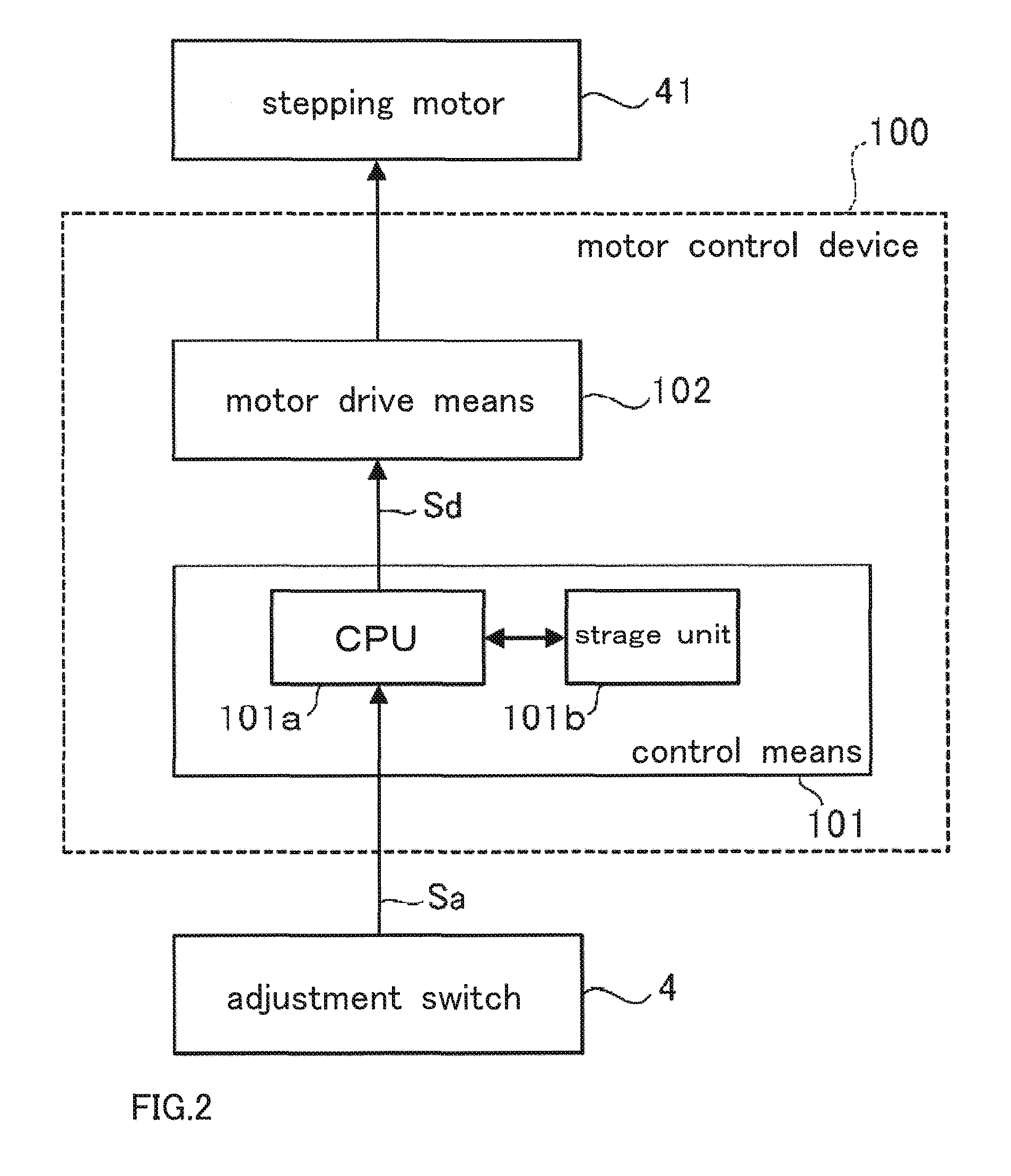
[0090]If the detected rotational position is within the n / 2 steps (step S205; Yes), the control means 101 cuts off excitation (step S206). Specifically, the control means 101 stops supply of a drive signal Sd to the motor drive means 102 so that the stepping motor 41 enters a non-excitation state. Thus, the rotor of the stepping motor 41 is rotated toward the previous stable excitation position by ...


PUM


Abstract

The purpose of the present invention is to cut down the travel distance of a display image on receiving a stop instruction intended for a stepping motor and thereby reduce a feeling of strangeness perceived by a user. A display device allows a user to view the image displayed on a display at a prescribed display position. The display device comprises: a stepping motor having a rotor including a magnet and driven by a micro-step drive method; a reflector which moves in accordance with the rotation of the rotor in the stepping motor so as to move the display position; and a motor control device. The motor control device identifies a rotational position of the rotor between adjacent stable excitation positions, and moves the rotor to reach the closer of the stable excitation positions on the basis of the identified rotational position on receiving a stop instruction intended for the stepping motor.

Description

RELATED APPLICATIONS[0001]This application is the the U.S. National Phase under 35 U.S.C. §371 of International Application No. PCT / JP2014 / 070861, filed on Aug. 7, 2014, which in turn claims the benefit of Japanese Application No. 2013-176774 filed on Aug. 28, 2013, the disclosures of which are incorporated by reference herein.TECHNICAL FIELD[0002]The present invention relates to a display device.BACKGROUND ART[0003]As a related art display device, for example, there is a vehicle display device disclosed in PTL 1. This vehicle display device is configured as a head-up display device in which a display projects display light onto a windshield of a vehicle to display a predetermined image with respect to a user (mainly, a driver) as a virtual image.[0004]In the display device disclosed in PTL 1, a reflecting mirror that reflects the display light from the display toward the front glass rotationally moves by a stepping motor, and thus, the position of a displayed image can be adjusted....

Claims


Application Information

Patent Timeline
IPC IPC(8): G02B26/08B60K35/00G02B27/01H02P8/22
CPCG02B26/0816B60K35/00G02B27/0101G02B27/0149H02P8/22G02B2027/0145G02B2027/0159
Inventor OGURO, YUJIUSHIDA, NORIHIKOMARUYAMA, MITSURU
Owner NIPPON SEIKI CO LTD
Why Eureka
Try Eureka