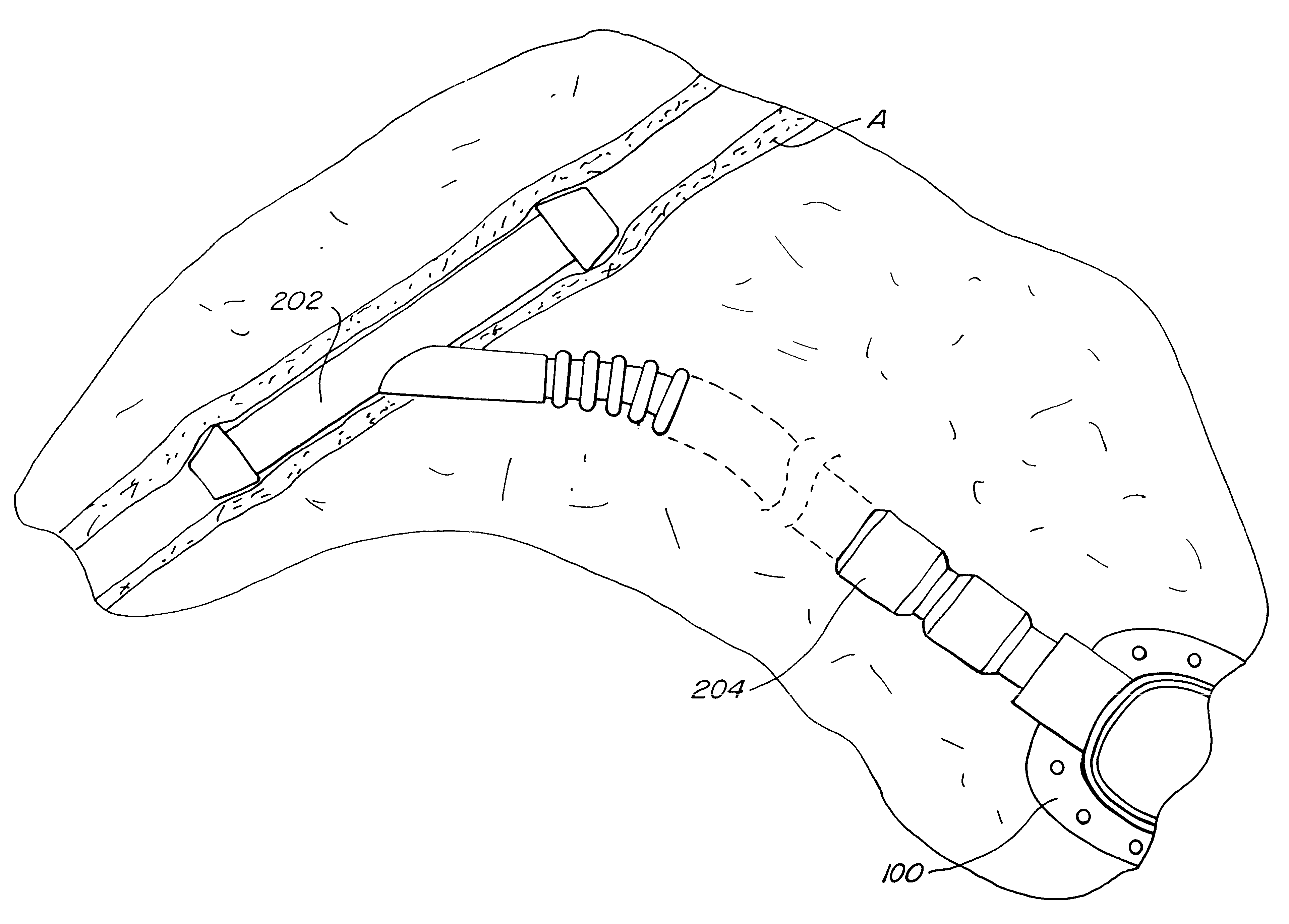
The arterial access cannula may be implanted either subcutaneously or transcutaneously. By transcutaneous, it is meant that a portion of the access leg will pass outwardly through the patient's
skin to permit direct arterial access using external
drug pumps, syringes, or other equipment. It will be appreciated, of course, that a
hemostasis valve must be provided on the access leg to prevent uncontrolled
blood loss. Usually, any transcutaneous use of the cannula of the present invention will be only for a short time.
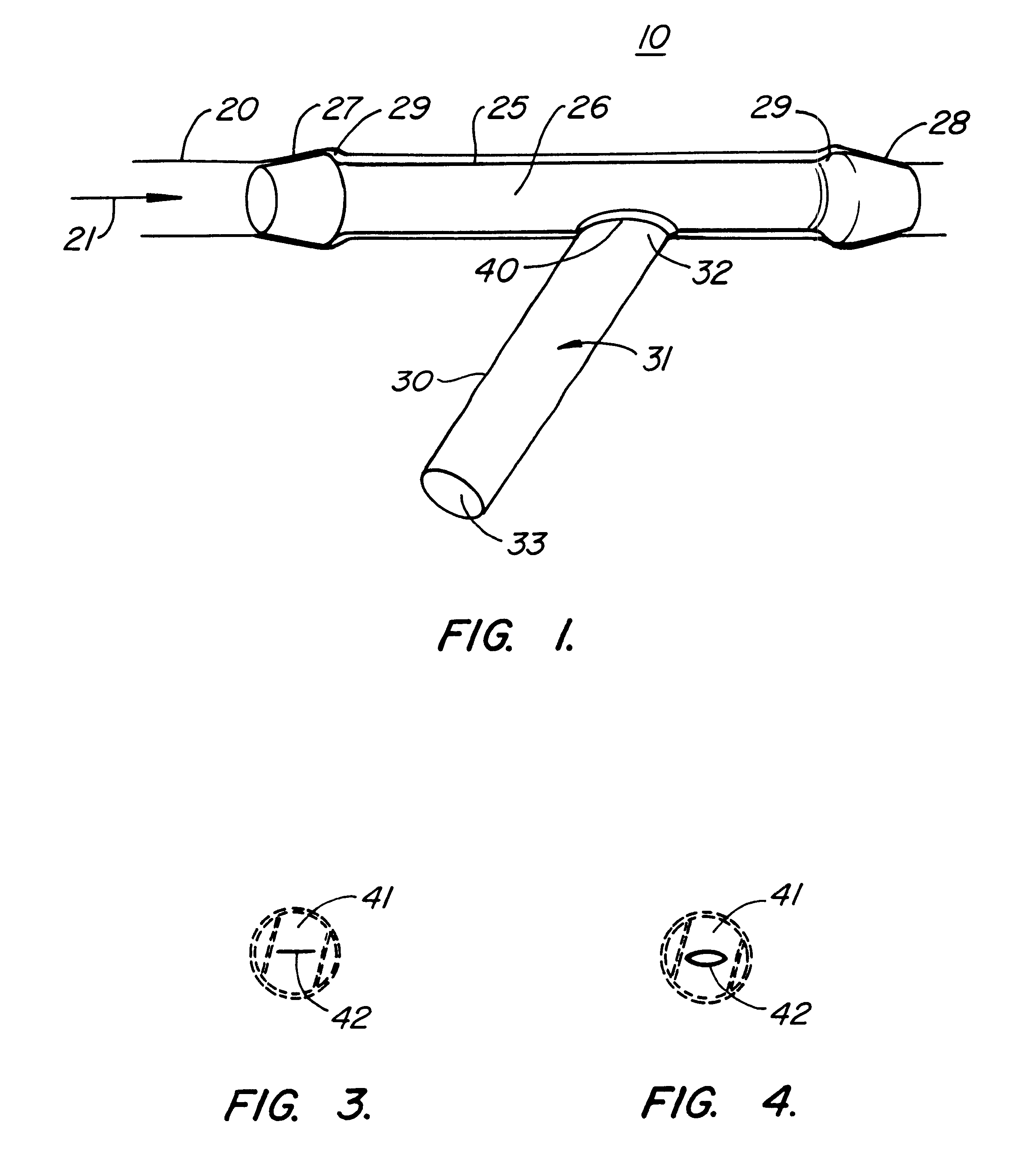
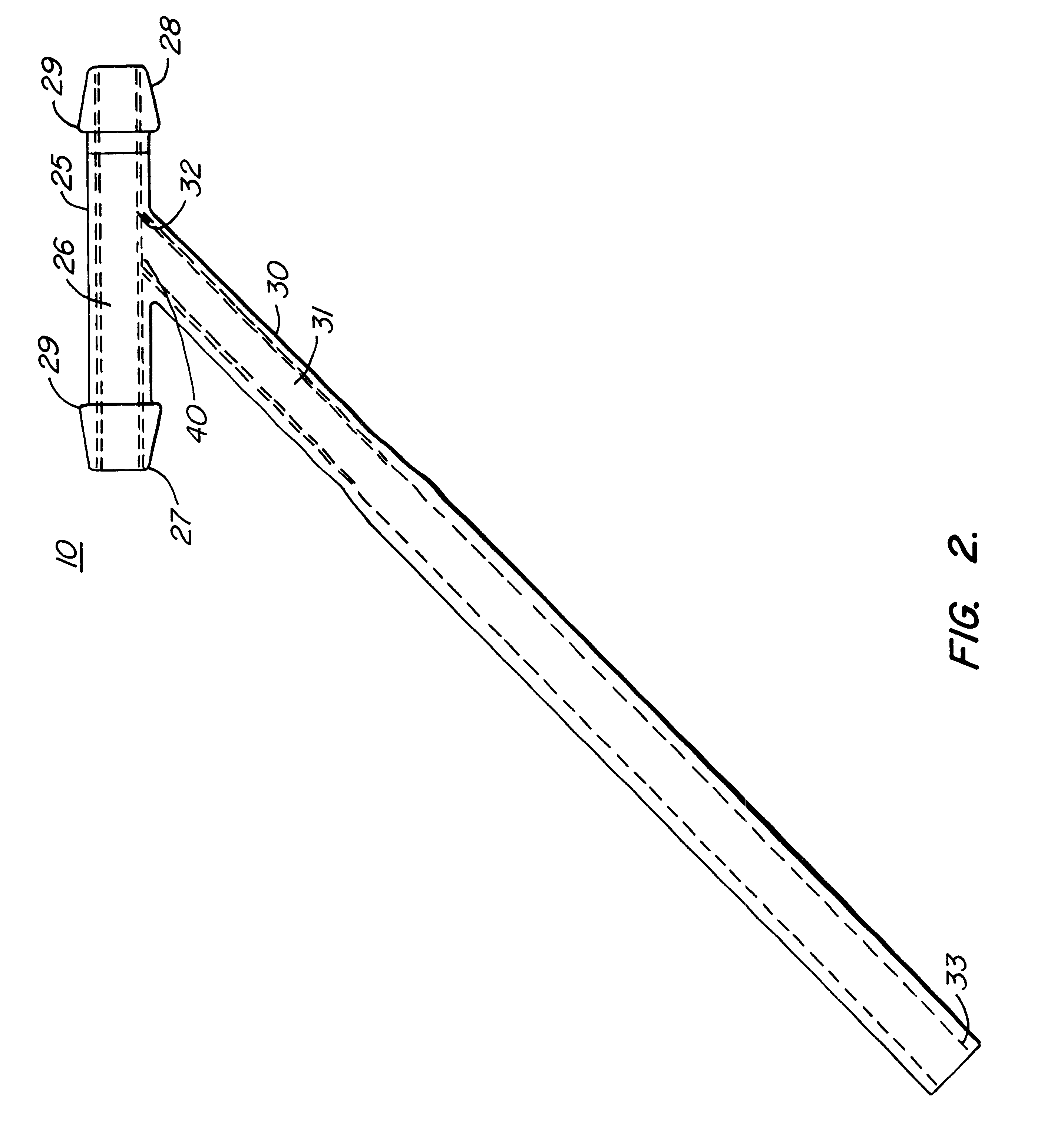
In all cases, the T-configured
arterial cannula of the present invention is an improvement over prior
indwelling catheters in a number of respects. The tubular body is firmly anchored within the
artery and not subject to being moved or dislodged by
blood flow. Thus, trauma to the
arterial wall from movement of the cannula is significantly lessened. Moreover, by assuring that the lumen of the tubular body has a cross-sectional shape and dimensions which closely match those of the
arterial lumen, smooth
blood flow through the cannula can be enhanced while the risk of
thrombus formation is substantially reduced.
In a preferred construction, the
arterial cannula will include an
isolation valve, at or near the junction between the access leg and the tubular body. The
isolation valve can be any type of valve that closes or inhibits flow between the tubular body lumen and the access leg lumen in the absence of a pressure drop therebetween. Thus, when blood is not being withdrawn and / or when drugs or other media are not being introduced, the
isolation valve will close and isolate the lumen of the access leg from
arterial blood flow. Such isolation is a significant
advantage since it reduces the risk of
thrombus formation within the access leg and thrombus release into the
arterial lumen. Often, it will be desirable to flush the lumen of the access leg with an anti-coagulant fluid after each use. The removal of static blood and the placement of the anti-coagulant fluid further decreases the risk of thrombus formation and release. The isolation valve may be in a variety of forms, including slit valves, flap valves, ball valves, and may further be configured to provide for one-way or bi-direction flow. For example, in the case of arterial cannulas used for withdrawing blood, it will often be advantageous to have a one-way isolation valve which permits blood flow from the tubular body into the access leg, but inhibits reverse flow of any materials from the access leg into the lumen. In the case of
drug and other infusions into the
artery, it may be desirable to provide a one-way isolation valve which permits such introduction, but prevents
reflux of blood into the access leg. A particularly preferred valve is a slit valve formed into the wall of the tubular body, as illustrated in detail hereinafter. When such a slit valve is closed, the inner profile of the tubular body lumen will be substantially smooth and free from discontinuities caused by the valve.
The
arterial cannula may be formed from any one or a combination of a variety of biocompatible materials. By biocompatible, it is meant that the material(s) will be suitable for a long term implantation within patient vasculature and tissue and will be free from
immunogenicity and
inflammatory response. Usually, the cannula will be formed in whole or in part from an
organic polymer, such as
silicone rubber, polyethylenes, polyurethanes, polyvinylchloride,
polytetrafluoroethylene (PTFE),
polysulfone, or the like. Portions of the cannula may be reinforced, for example the access leg may include circumferential reinforcement to enhance its hoop strength without significantly diminishing flexibility. Such reinforcement may take the form of a
helical wire or ribbon, axially spaced-apart hoops, or the like. Preferably, the reinforcement may be achieved by molding the access leg to incorporate circumferential corrugation, i.e. a plurality of axially spaced-apart circumferential ribs along all or a portion of its lengths. In all cases, it is desirable that the internal lumen of the access leg and the tubular body remain as smooth as possible to avoid disturbances to blood flow.
In a preferred aspect of the present invention, at least a portion of the access leg of the arterial cannula will be sufficiently compliant so that substantially no forces are transmitted from the access leg back into the tubular body. For proper functioning of the arterial cannula, it is important that the tubular body remain properly aligned within the
arterial lumen. This can be achieved by fabricating at least a portion of the access leg adjacent to the tubular body to have a low
bending stiffness. The hoop strength of the access tube, in contrast, should remain relatively high, being at least sufficient to maintain patency of its lumen at internal pressures below -250 mmHg, preferably below -400 mmHg. Use of the
helical reinforcement designs described above helps assure that the access leg can be sufficiently flexible while retaining sufficient strength.

