
Vehicle headlamp

a headlamp and vehicle technology, applied in the field of vehicles, to achieve the effect of improving the visibility of overhead signs and contributing to traffic safety

Active Publication Date: 2012-11-15
ICHIKOH IND LTD
View PDF8 Cites 4 Cited by
  • Summary
  • Abstract
  • Description
  • Claims
  • Application Information

AI Technical Summary

Benefits of technology

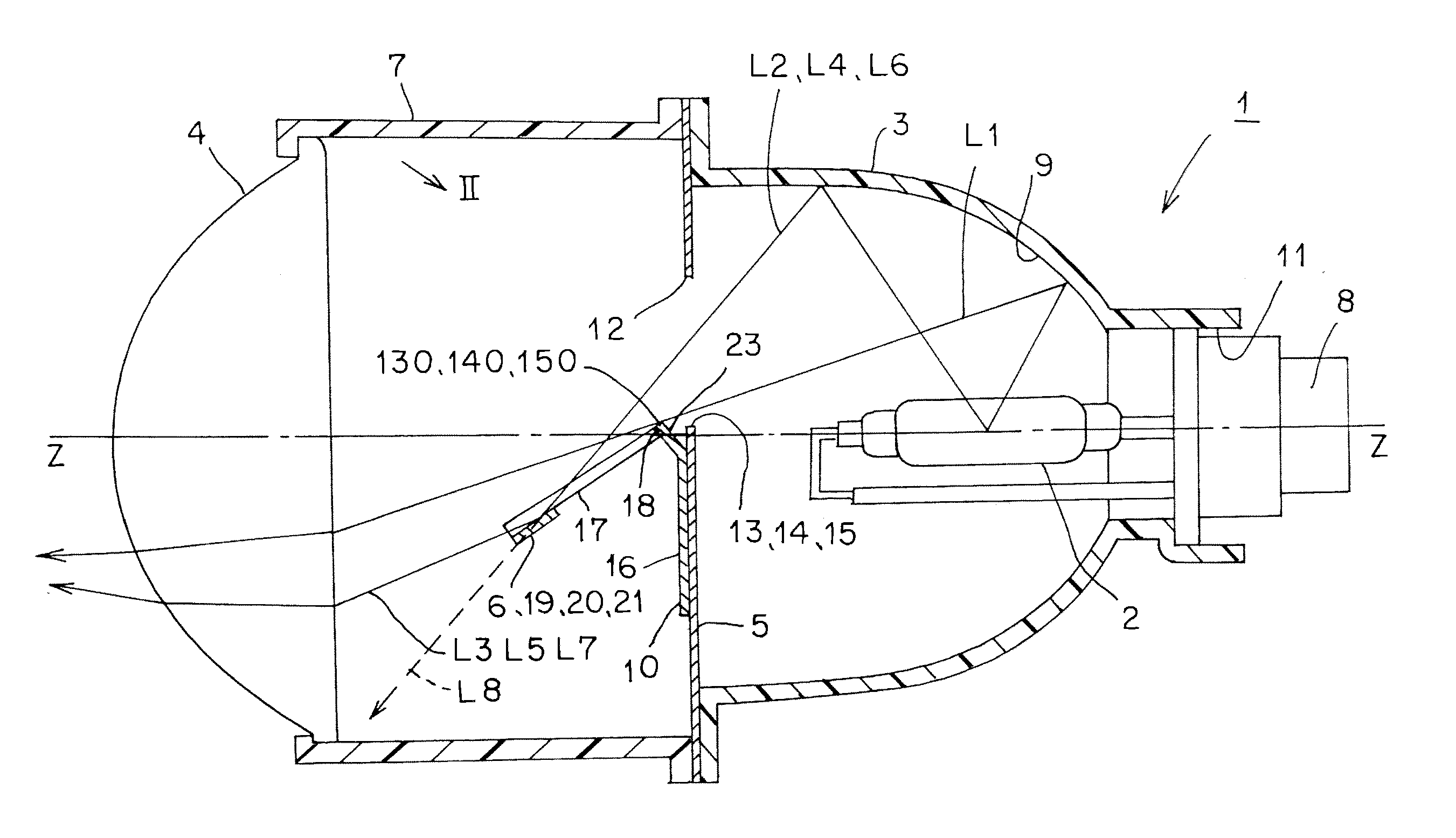
[0011]The vehicle headlamp according to the first aspect of the present invention is capable of transversely spreading a light distribution pattern for overhead sign by means of a recessed reflection surface of a reflection member, thus making it possible to control light distribution so that light is distributed to a predetermined point.
[0012]In the vehicle headlamp according to the second aspect of the present invention, an area of the second recessed reflection surface is smaller than an area of the first recessed reflection surface; and therefore, reflection light having passed through the window portion on the second horizontal edge side and reflected by the second recessed reflection surface onto the cruising lane side is less than reflection light having passed through the first horizontal edge side and reflected by the first recessed reflection surface onto the cruising lane side. However, the second horizontal edge is positioned to be lower than the first horizontal edge; and therefore, the light having passed through the window portion on the second horizontal edge side is more than the light having passed through the window portion on the first horizontal edge side. As a result, in the vehicle headlamp according to the second aspect of the present invention, the light having passed through the window portion on the first horizontal edge side (less light than the light having passed through the window portion on the second horizontal edge side) is reflected on the first recessed reflection surface to form a portion on an opposite lane side by means of the reflection light (more reflection light than the reflection light reflected on the second reflection surface), whereas the light having passed through the window portion on the second horizontal edge side (more light than the light having passed through the window portion on the first horizontal edge side) is reflected on the second recessed reflection surface to form a portion on the cruising lane side by means of the reflection light (less reflection light than the reflection light reflected on the first reflection surface), and the light having passed through the window portion on the central oblique edge side (more light than the light having passed through the window portion on the first horizontal edge side and less light than the light having passed through the window portion on the second horizontal edge side) is reflected on a third recessed reflection surface to form a central connecting portion in the light distribution patterns for overhead sign by means of the reflection light (less light than the reflection light reflected on the first reflection surface and more light than the reflection light reflected on the second reflection surface). In this manner, the vehicle headlamp according to the second aspect of the present invention is capable of setting the entire light distribution patterns for overhead sign at a substantially uniform brightness, and visibility of an overhead sign is improved, making it possible to contribute to traffic safety.

Problems solved by technology

As described above, in such a vehicle headlamp of projection type, there is a problem that it is necessary that light be distributed to a predetermined point in a state in which the light is transversely spread.

Method used


Image

  • Vehicle headlamp
  • Vehicle headlamp
  • Vehicle headlamp

Examples


first embodiment

Description of Configuration

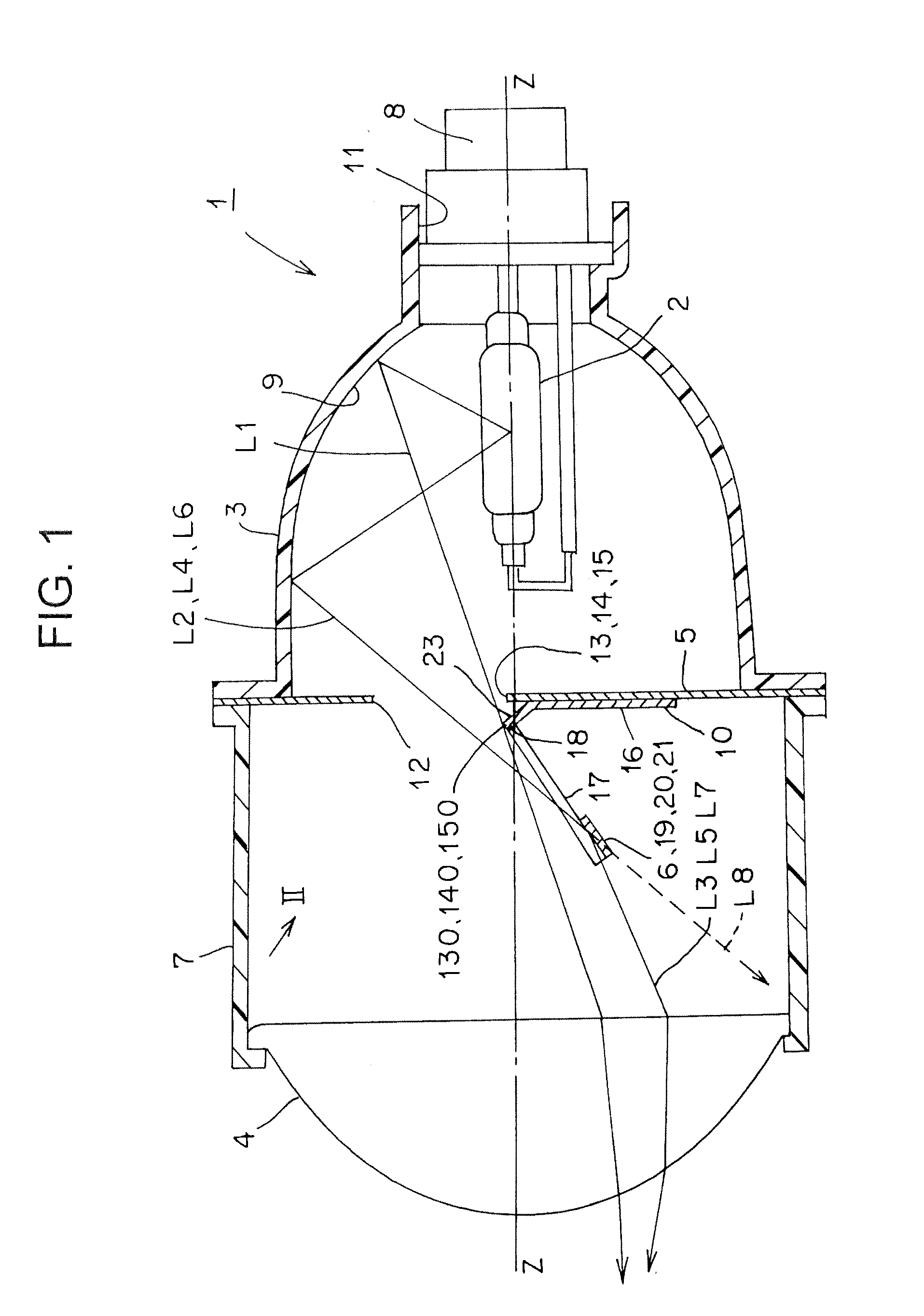
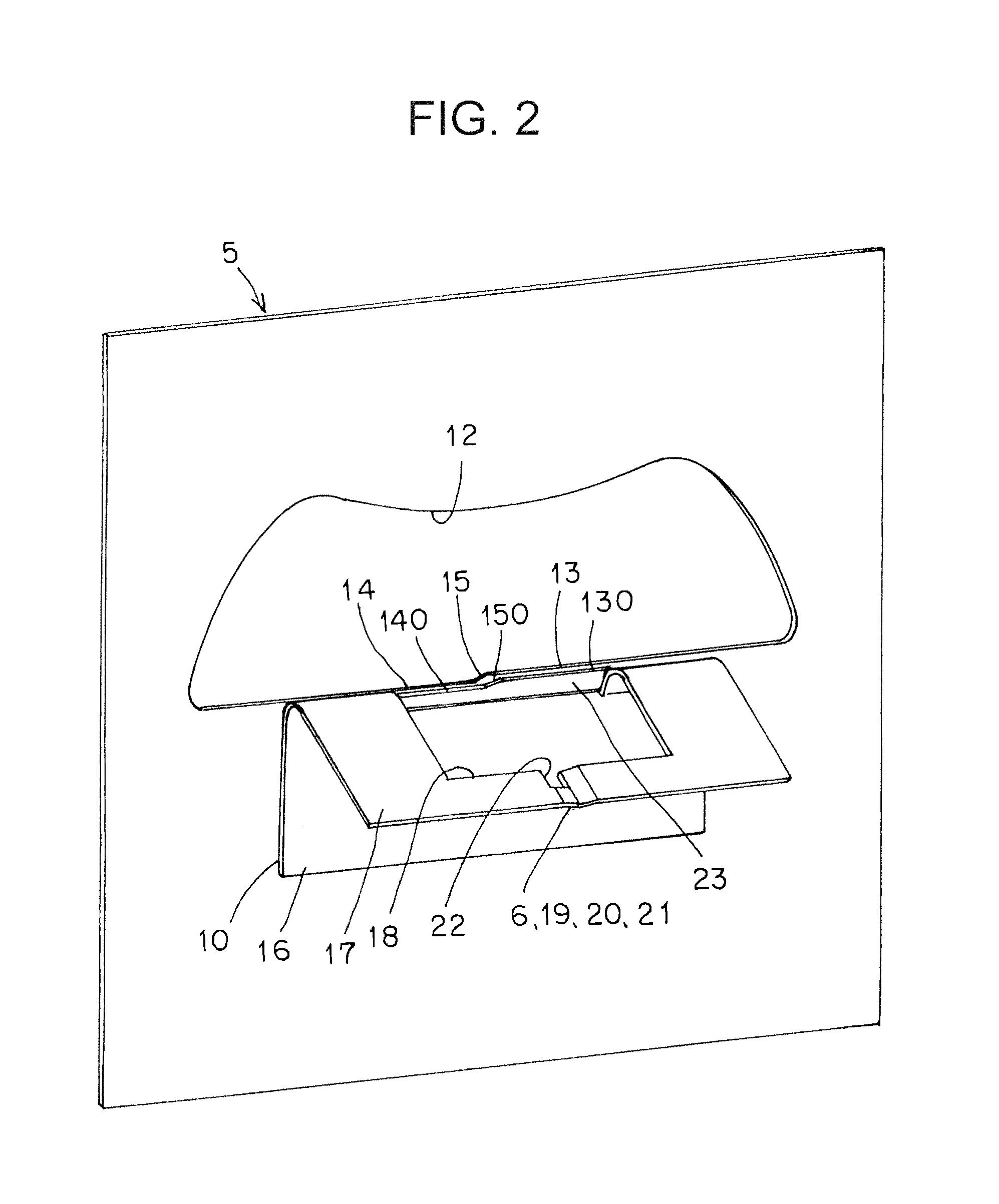
[0027]FIG. 1 to FIG. 9 each show a vehicle headlamp according to a first embodiment of the present invention. Hereinafter, a configuration of the vehicle headlamp according to the first embodiment will be described. In FIG. 1, reference numeral 1 designates a vehicle headlamp of projection type according to the first embodiment (such as a headlamp or a fog lamp, for example). The vehicle headlamp 1 is equipped at a respective one of the right and left of a front part of an automobile (a vehicle). The vehicle headlamp 1 is a vehicle headlamp for left side passageway. FIG. 3A is a plan view of a shade and a reflection member, FIG. 3B is a front view of the shade and the reflection member, and FIG. 3C is a right side view of the shade and the reflection member.

[0028]The vehicle headlamp 1, as shown in FIG. 1, is provided with: a discharge lamp 2 serving as a light source; a reflector 3; a projection lens (a focusing lens and a convex lens) 4; a shade 5; a re...

second embodiment

Description of Second Embodiment

[0063]FIG. 10 to FIG. 12 each show a vehicle headlamp according to a second embodiment of the present invention. Hereinafter, the vehicle headlamp in the second embodiment will be described. In the figures, like constituent elements are designated by like reference numerals assigned in FIG. 1 to FIG. 9.

[0064]According to the aforementioned vehicle headlamp 1 of the first embodiment, an area of the second recessed reflection surface 20 of the reflection member 6 is smaller than an area of the first recessed reflection surface 19 by means of a cutout 22. On the other hand, according to a vehicle headlamp of the second embodiment, a V-shaped valley is shifted (offset) by a width B to the side of the second horizontal edges 14 and 140 and the central oblique edges 15 and 150 with respect to the centerline O, and a width C on the side of a second recessed reflection surface 200 of a reflection member 600 is smaller than a width D on the side of a first rec...


PUM


Abstract

An object of the present invention is to control light distribution so that light is distributed to a predetermined point while a light distribution pattern for overhead is transversely spread. The present invention includes a discharge lamp, a reflector, a projection lens, a shade, and a reflection member. At a window portion of the shade, edges, are provided for forming cutoff lines CL1, CL2, and CL3. The reflection member is disposed between the projection lens and the shade. At the reflection member, recessed reflection surfaces are provided for transversely spreading a light distribution pattern OSP for overhead sign. As a result, the present invention is capable of controlling light distribution so that light is distributed to a predetermined point in a state in which the light distribution pattern OSP for overhead sign is transversely spread.

Description

CROSS-REFERENCE TO RELATED APPLICATIONS[0001]This application claims priority of Japanese Patent Application No. 2011-106598 filed on May 11, 2011. The contents of this application are incorporated herein by reference in their entirety.BACKGROUND OF THE INVENTION[0002]1. Field of the Invention[0003]The present invention relates to a vehicle headlamp of projector type, which is adapted to emit a light distribution pattern having one or more cutoff lines and a light distribution pattern for overhead sign, forward of a vehicle.[0004]2. Description of the Related Art[0005]A vehicle headlamp of such projector type is conventionally known (for example, Japanese Unexamined Patent Application Publication No. 2008-21463). Hereinafter, a conventional vehicle headlamp will be described. The conventional vehicle headlamp is a headlamp in which part of reflection light from a reflector is shaded by means of a shade, a light distribution pattern having cutoff lines is formed by means of the remai...

Claims


Application Information

Patent Timeline
Patent Type & Authority Applications(United States)
IPC IPC(8): B60Q1/00F21Y101/00
CPCF21S48/145F21S41/43F21W2102/18
Inventor MURAKAWA, KAZUHIRO
Owner ICHIKOH IND LTD
Learn More