Vehicle lighting fixture

a technology for lighting fixtures and vehicles, applied in the direction of point-like light sources, lighting and heating apparatuses, etc., can solve the problems of lowering the visibility of drivers or misunderstanding driving conditions, uneven light intensity in the produced light distribution pattern, and difficult to dispose of the plurality of light sources without any gap, etc., to prevent light intensity unevenness, more accurate light distribution control, and reduce the formation of darkened areas

Active Publication Date: 2018-02-27
STANLEY ELECTRIC CO LTD
View PDF12 Cites 0 Cited by
  • Summary
  • Abstract
  • Description
  • Claims
  • Application Information

AI Technical Summary

Benefits of technology

[0007]The presently disclosed subject matter was devised in view of these and other problems and features in association with the conventional art. According to an aspect of the presently disclosed subject matter, a vehicle lighting fixture can control the light distribution with higher accuracy while suppressing the light intensity unevenness of the light distribution even with a plurality of light sources used.
[0014]This configuration can suppress the formation of darkened areas formed corresponding to the gaps between the adjacent light sources, and in turn, prevent the light intensity unevenness in the produced light distribution pattern. Appropriate adjustment of the shape and arrangement of the prisms can achieve more accurate light distribution control.
[0015]Thus, the vehicle lighting fixture with the above-mentioned configuration can control the light distribution with higher accuracy while suppressing the light intensity unevenness of the light distribution even with the plurality of light sources used.

Problems solved by technology

When a plurality of light sources are arranged, it is absolutely difficult to dispose the plurality of light sources without any gap therebetween.
Thus, if such a plurality of light sources with a gap therebetween are turned on, the irradiation area may include darkened areas due to the gaps between the adjacent light sources, thereby resulting in light intensity unevenness in the produced light distribution pattern.
When such a vehicle lighting fixture is used as a headlamp or a signal light, there may be a case of lowering the visibility of a driver or misunderstanding of driving conditions by a driver.
This results in destructing the safety of driving.
However, the vehicle lighting fixture of Japanese Patent Application Laid-Open No. 2006-522440 (or U.S. 2006 / 0198118 A1 corresponding thereto) utilizes the diffusion function of light by the auxiliary material, it is difficult to control the degree of diffusion.
Thus, when the disclosed vehicle lighting fixture is applied to a variable light distribution type headlamp, the light from the turned-on light source may be unintentionally directed in an optical path from a turned-off light source.
In this case, an accurate light control may be hindered.

Method used


Image

  • Vehicle lighting fixture
  • Vehicle lighting fixture
  • Vehicle lighting fixture

Examples


Embodiment Construction

[0026]A description will now be made below to vehicle lighting fixtures of the presently disclosed subject matter with reference to the accompanying drawings in accordance with exemplary embodiments.

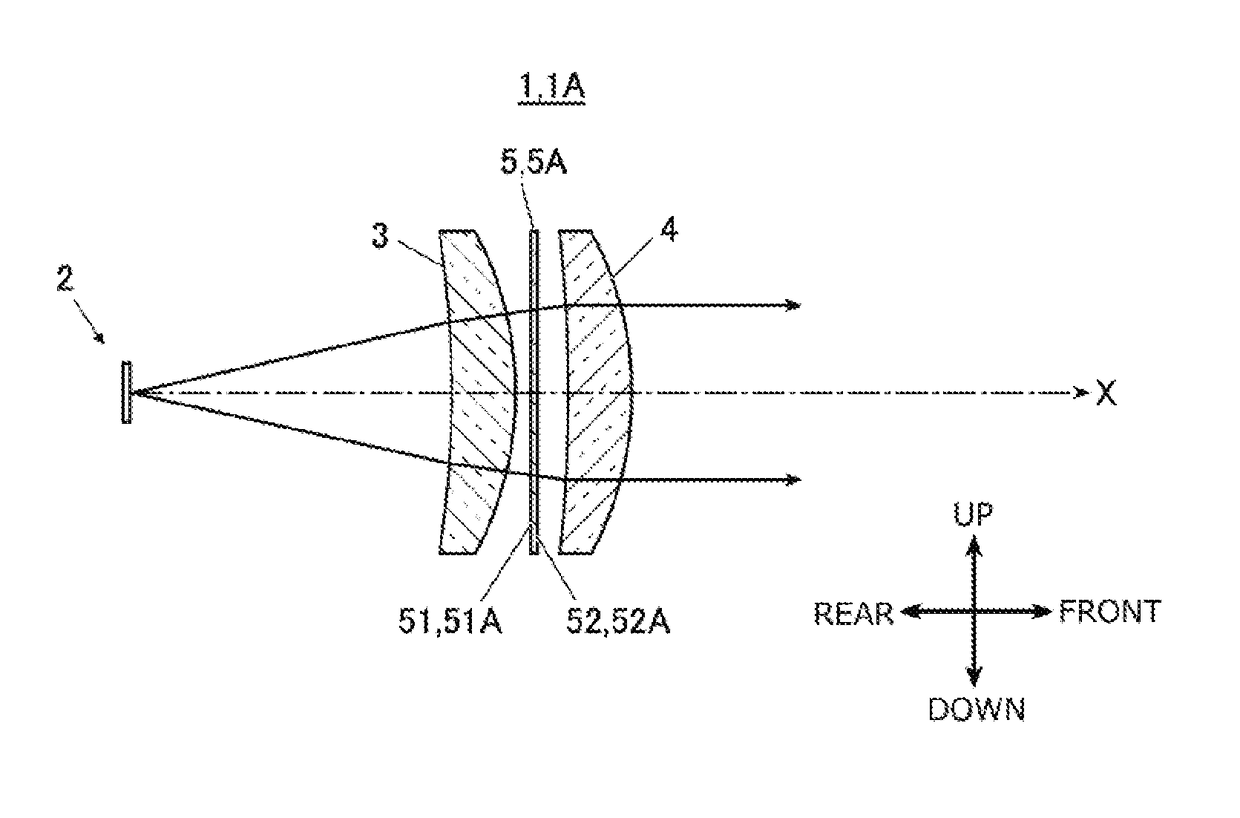
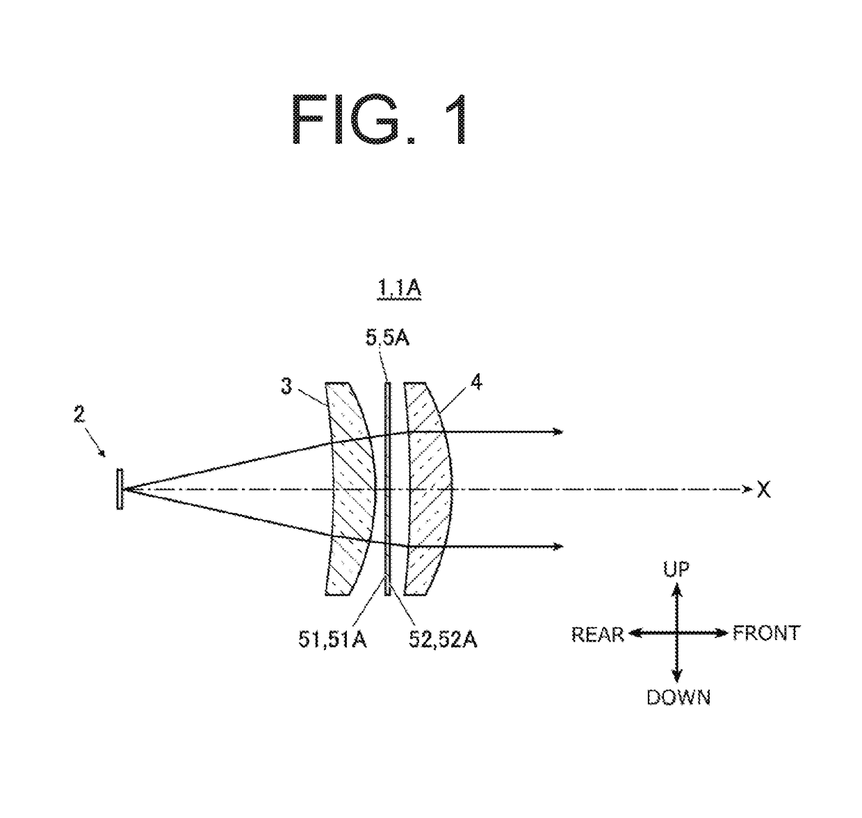
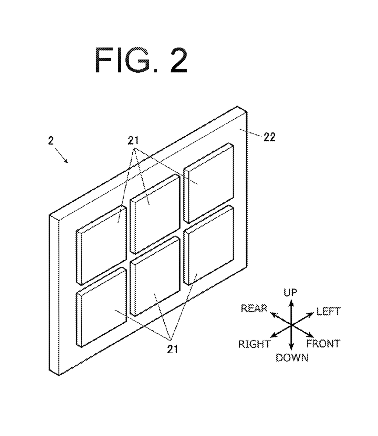
[0027]FIG. 1 is a cross-sectional view illustrating essential parts of a vehicle lighting fixture 1 made in accordance with the principles of the presently disclosed subject matter, and FIG. 2 is a perspective view illustrating an LED array included in the vehicle lighting fixture 1. FIGS. 3A, 3B, and 3C are diagrams for describing an image shifter 5 that can be provided to the vehicle lighting fixture 1. FIG. 3A is a perspective view of the image shifter 5 when seen from its rear side. FIG. 3B is a perspective view of the image shifter 5 when seen from its front side, and FIG. 3C is a partial cross-sectional view of its prisms formed in the surface of the image shifter 5. Note that in FIG. 3C, the ratio of the height to the width of the illustrated prism is made larger than that in an a...


PUM


Abstract

A vehicle lighting fixture can control the light distribution with higher accuracy while suppressing the light intensity unevenness of the light distribution even with a plurality of light sources used. The vehicle lighting fixture can include: a plurality of LED elements arranged in a vertical direction and a lateral direction; a projector lens assembly including two projector lenses disposed in front of the plurality of LED elements and configured to project light emitted from the plurality of LED elements forward; and an image shifter disposed in an optical path from the plurality of LED elements to a position forward of the projector lenses. The image shifter can include a plurality of prisms configured to widen light source images of the plurality of LED elements in the vertical and lateral directions.

Description

[0001]This application claims the priority benefit under 35 U.S.C. § 119 of Japanese Patent Application No. 2015-115378 filed on Jun. 8, 2015, which is hereby incorporated in its entirety by reference.TECHNICAL FIELD[0002]The presently disclosed subject matter relates to vehicle lighting fixtures to be mounted on a vehicle body, and in particular, to a vehicle lighting fixture including a plurality of light sources arranged in a predetermined direction.BACKGROUND ART[0003]There are conventionally known vehicle lighting fixtures to be mounted on a vehicle body having a plurality of light sources such as light emitting diodes arranged, for example, those described in Japanese Patent Application Laid-Open No. 2001-266620 (or U.S. 2001 / 0019486 A1 corresponding thereto). In recent years, variable light distribution type headlamps that can change its light distribution according to the surrounding environment have been widespread. In general, this type of vehicle lighting fixture can be c...

Claims


Application Information

Patent Timeline
Patent Type & Authority Patents(United States)
IPC IPC(8): B60Q1/00B60Q3/00B60Q1/04F21V5/00
CPCF21S41/143F21S41/141B60Q1/0483F21V5/005F21S41/285F21S43/26F21S41/25F21S41/265F21S41/155F21S43/14F21S41/145F21Y2101/00F21S41/663F21S41/153F21S43/145
Inventor OHNO, MASAFUMI
Owner STANLEY ELECTRIC CO LTD
Why Eureka
Try Eureka