Lighting control device, lighting control method and lighting tool for vehicle

Active Publication Date: 2020-05-19
STANLEY ELECTRIC CO LTD
View PDF12 Cites 1 Cited by
  • Summary
  • Abstract
  • Description
  • Claims
  • Application Information

AI Technical Summary

Benefits of technology

[0012]In the lighting control device of the aspect of the present invention, the light distribution controller may control a light shielding range with respect to the vehicle located in front by controlling the light distribution with respect to the front side.
[0017]According to the aspect of the present invention, it is possible to provide a lighting control device, a lighting control method and a lighting tool for a vehicle that are capable of controlling a light distribution pattern of a headlamp for a host vehicle with respect to a predetermined direction of a vehicle located in front.

Problems solved by technology

However, in the technology disclosed in Japanese Unexamined Patent Application, First Publication No. 2017-013516, a range of a direction in which the calculated radiation of the headlight is to be suppressed is a leftward / rightward direction, and a range of a direction in which radiation of the headlight with respect to the upward / downward direction of the vehicle located in front is to be suppressed cannot be calculated.

Method used


Image

  • Lighting control device, lighting control method and lighting tool for vehicle
  • Lighting control device, lighting control method and lighting tool for vehicle
  • Lighting control device, lighting control method and lighting tool for vehicle

Examples


first embodiment

[0033]A lighting control device according to an embodiment is mounted in a vehicle. In the embodiment, while an automobile is shown as an example of the vehicle, a motorcycle, a bicycle, a micro-miniature mobility device, a personal mobility device, or the like, may be provided as the vehicle.

[Schematic Configuration of Automobile]

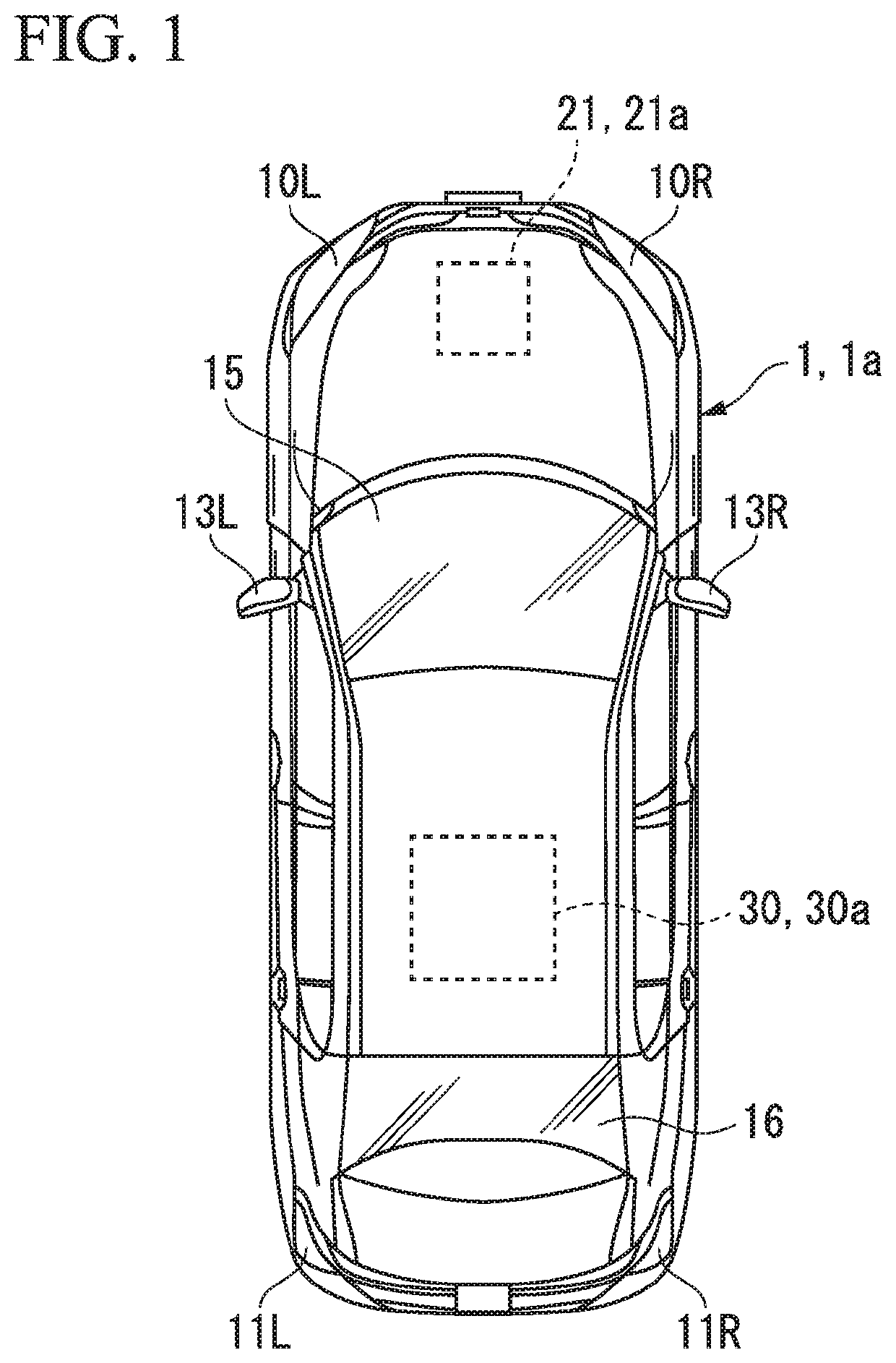
[0034]FIG. 1 is a view showing a schematic configuration of an automobile 1 according to a first embodiment.

[0035]The automobile 1 includes a headlight on a left side (in the embodiment, referred to as a left headlight section 10L), a headlight on a right side (in the embodiment, referred to as a right headlight section 10R), a tail light on a left side (in the embodiment, referred to as a left tail light section 11L), a tail light on a right side (in the embodiment, referred to as a right tail light section 11R), a sideview mirror on a left side (in the embodiment, referred to as a left sideview mirror 13L), a sideview mirror on a right side (in the embod...

second embodiment

[0122]FIG. 1 may be applied as a schematic configuration of an automobile 1a according to a second embodiment. However, the automobile 1a according to the second embodiment is distinguished from the automobile 1 according to the first embodiment in that a vehicle front outside detection section 21a is provided instead of the vehicle front outside detection section 21 and a lighting control device 30a is provided instead of the lighting control device 30.

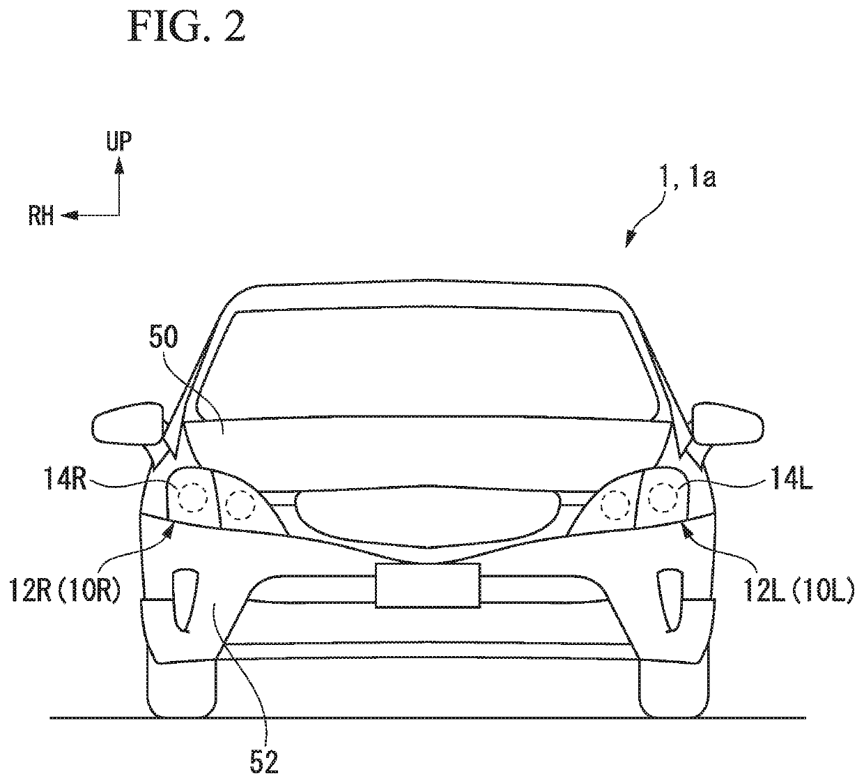
[0123]FIG. 2 may be applied as a front portion of the automobile 1a to which a lighting system 100a according to the second embodiment is applied.

[Schematic Functional Configuration of Lighting System of Automobile]

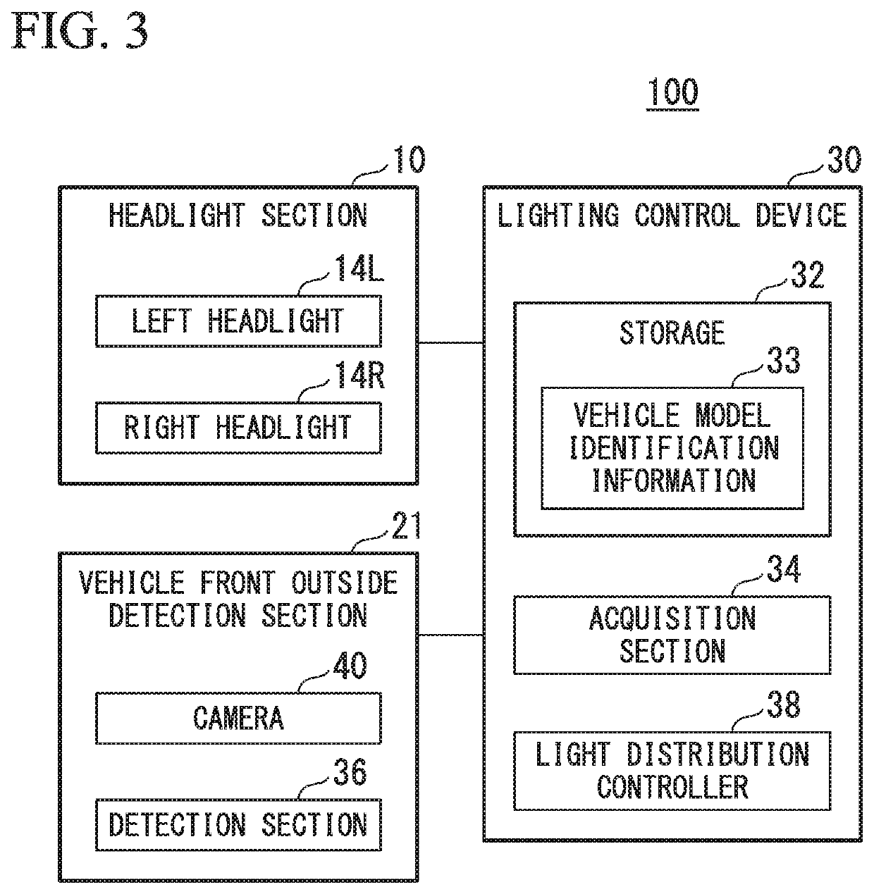
[0124]FIG. 10 is a block diagram showing a schematic functional configuration of the lighting system 100a provided in the automobile 1a according to the second embodiment.

[0125]The lighting system 100a includes the headlight section 10, the lighting control device 30a and the vehicle front outside detection section 21a. In...


PUM


Abstract

A lighting control device configured to control a radiation state of light from a headlamp for a vehicle includes a vehicle model information acquisition section configured to acquire vehicle model information of a vehicle located in front in front of a host vehicle, a distance detection section configured to detect a distance between the vehicle located in front and the host vehicle, and a light distribution controller configured to control a light distribution with respect to a side in front of the host vehicle by the headlamp for a vehicle on the basis of the vehicle model information and the distance.

Description

CROSS-REFERENCE TO RELATED APPLICATION[0001]Priority is claimed on Japanese Patent Application No. 2018-009301, filed Jan. 24, 2018, the content of which is incorporated herein by reference.BACKGROUND OF THE INVENTIONField of the Invention[0002]The present invention relates to a lighting control device, a lighting control method, and a lighting tool for a vehicle.Description of Related Art[0003]A headlight for an automobile has two functions of, for example, a traveling beam (a so-called high beam) and a passing beam (a so-called low beam).[0004]In recent years, an adaptive driving beam (ADB) has been developed, and a lamp having a function of shielding a portion of a preceding vehicle or an oncoming vehicle present at a side in front of a vehicle from light and holding a region of a traveling beam has been proposed.[0005]In the ADB, when a side in front of the vehicle is imaged and an object to be shielded from light is detected, a signal is sent to a light control module (LCM) and...

Claims


Application Information

Patent Timeline
Patent Type & Authority Patents(United States)
IPC IPC(8): B60Q1/14
CPCB60Q1/143B60Q1/1423B60Q2300/43B60Q2300/056B60Q2300/41
Inventor KAMBARA, TAKESHI
Owner STANLEY ELECTRIC CO LTD
Why Eureka
Try Eureka