Code Generating Apparatus, Reference Signal Generating Apparatus, and Methods thereof

Active Publication Date: 2012-11-15
FUJITSU LTD
View PDF2 Cites 5 Cited by
  • Summary
  • Abstract
  • Description
  • Claims
  • Application Information

AI Technical Summary

Benefits of technology

[0039]According to the methods and apparatuses for generating codes proposed in the present invention, RS randomization may be enhanced, the problem of RS power imbalance may be removed, the requirement on orthogonality at the two dimensions of both the time and frequency may be satisfied, and more robust channel estimation properties may be provided.

Problems solved by technology

The Long Term Evolution-Advanced (LTE-Advanced) next-generation wireless communication system of 3GPP requires the downlink to provide a peak rate of 1 Gps and a peak spectral efficiency of 30 bps / Hz, and this brings about challenges to the physical layer transmission scheme of the system.
With the increase in motion speed of a mobile station, the change in channel responses of the M number of OFDM symbols accordingly increases, and orthogonality of the spectrum-spread code is damaged, whereby data transmission layers interfere with one another, and the precision in channel estimation is lowered.

Method used


Image

  • Code Generating Apparatus, Reference Signal Generating Apparatus, and Methods thereof
  • Code Generating Apparatus, Reference Signal Generating Apparatus, and Methods thereof
  • Code Generating Apparatus, Reference Signal Generating Apparatus, and Methods thereof

Examples


Embodiment Construction

[0058]Preferred embodiments of the present invention are described in greater detail below with reference to the drawings. Details and functions unnecessary to the present invention are not mentioned in the description to avoid confused comprehension of the present invention.

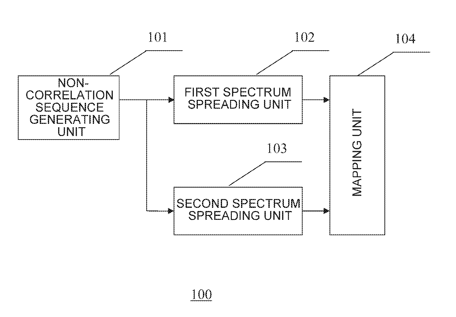
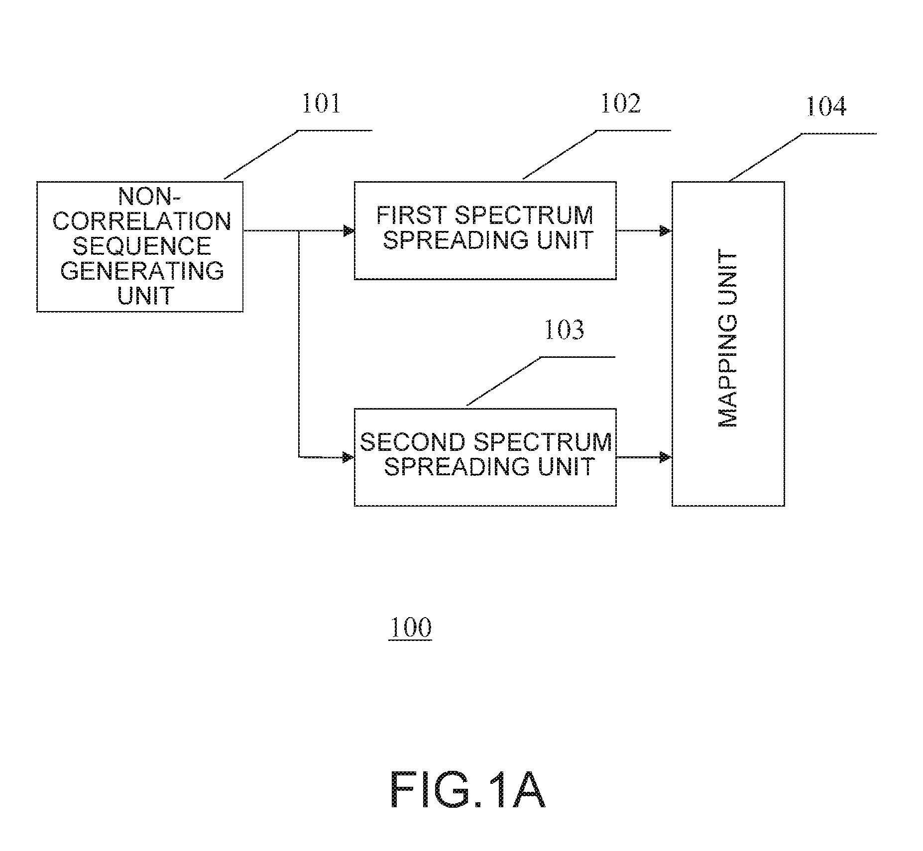
[0059]FIG. 1A is a schematic diagram illustrating a demodulation reference signal (DMRS) generating apparatus according to one embodiment of the present invention. The DMRS is an example of reference signals (RS) used for demodulation. As shown in FIG. 1A, the DMRS generating apparatus 100 according to one embodiment of the present invention includes a non-correlation sequence generating unit 101, a first spectrum spreading unit 102, a second spectrum spreading unit 103 and a mapping unit 104.

[0060]The non-correlation sequence generating unit 101 is configured to generate a non-correlation sequence for RS, which sequence should have ideal correlation (relatively small or even zero). The non-correlation sequence ...


PUM


Abstract

A demodulation reference signal generator includes a non-correlation sequence generator to generate a non-correlation sequence for RS of a first resource block; a first spectrum spreading unit to spread spectrums of elements in the non-correlation sequence for RS to be mapped to a first frequency resource of the first resource block, by using a first group of codes; a second spectrum spreading unit to spread spectrums of elements in the non-correlation sequence for RS to be mapped to a second frequency resource of the first resource block, using a second group of Codes; the first and second frequency resources are adjacent frequency resources used for RS transmission in the first resource block, and the first and second groups of Codes are mirrors in column to each other; and a mapping unit to map the spectrum-spread elements to the first and second frequency resources.

Description

CROSS-REFERENCE TO RELATED APPLICATIONS[0001]The present application is a continuation of PCT Application No. PCT / CN2010 / 070087, filed on Jan. 8, 2010, the content of which is incorporated herein by reference for all purposes.FIELD OF THE INVENTION[0002]The present invention relates to transmission technologies in the wireless communication system, and more particularly, to a code generating apparatus, a reference signal generating apparatus, and methods thereof used in Long Term Evolution and Long Term Evolution-Advanced systems.BACKGROUND OF THE INVENTION[0003]The Long Term Evolution-Advanced (LTE-Advanced) next-generation wireless communication system of 3GPP requires the downlink to provide a peak rate of 1 Gps and a peak spectral efficiency of 30 bps / Hz, and this brings about challenges to the physical layer transmission scheme of the system. A multiple input multiple output (MIMO) multi-antenna system supports transmission of parallel data streams, thereby greatly enhancing th...

Claims


Application Information

Patent Timeline
IPC IPC(8): H04B1/707
CPCH04J13/004H04J13/0062H04J13/14H04L5/0016H04B2201/707H04L27/2613H04B1/707H04J13/12H04J13/18H04L5/0051H04L27/26H04L5/0048
Inventor WANG, YIZHANG, YUANTAOZHOU, HUAWU, JIANMING
Owner FUJITSU LTD
Why Eureka
Try Eureka