Vehicle Bumper

a technology for bumpers and vehicles, applied in the field of vehicles, can solve the problems of sink marks in the wall on the outer side of the bumper, intruders into the bumper, dirties that portion, etc., and achieve the effects of increasing the rigidity of the attachment flange, enlarge the water drainage hole, and increasing the strength of the depression

Inactive Publication Date: 2012-11-22
SUZUKI MOTOR CORP
View PDF3 Cites 19 Cited by
  • Summary
  • Abstract
  • Description
  • Claims
  • Application Information

AI Technical Summary

Benefits of technology

[0011]A vehicle bumper is provided that can increase the rigidity while ensuring a superior drainage capability in the vicinity of the location where the bumper is attached to a side face member. A vehicle bumper includes a middle portion extending in vehicle width direction, two lateral portions extending from the two ends of the middle portion towards side face members (front fender panels), an upper flange protruding inward, with respect to a vehicle body, from an upper edge of the lateral portions, an attachment flange that is continuous with the upper flange near an end of the lateral portions and protruding further inside the vehicle body than the upper flange, a long groove formed by a depression in an upper face of the upper flange near the attachment flange along the upper edge of the lateral portions, at least one rib that partitions the long groove in vehicle width direction into a plurality of depressions, and a plurality of water drainage holes formed respectively in the plurality of depressions.

Problems solved by technology

Thus, since the bumper is a member that is arranged near the wheels, mud water that is drawn up by the wheels when driving in rainy weather may intrude into the bumper.
Mud water or rain water (simply referred to as “water” below) intruding into the bumper may become a cause of rust, if it accumulates inside the bumper, in particular at a portion connected to the side face members, and if it flows down along the surface of the bumper, it dirties that portion.
Thus, when flanges are erected extending from the walls on the inner side of the bumper towards the inner side with respect to the vehicle interior, sink marks may be generated in the wall on the outer side of the bumper.
However, when a portion of the walls is removed, then the rigidity will of course decrease in the vicinity thereof, so that when the bumper is fastened to the side face members (the vehicle body), there is the risk that the flanges are deformed due to the load of the bumper.
However, if such a rib is provided, then there is the risk that this blocks the drainage path for draining water, lowering the drainage capability.
Thus, it is necessary to provide a new drainage hole to ensure the drainage capability, and forming this drainage hole, in turn, lowers the rigidity.
Thus, in conventional bumpers, it has been difficult to achieve both superior drainage capability and rigidity at the same time.

Method used


Image

  • Vehicle Bumper
  • Vehicle Bumper
  • Vehicle Bumper

Examples


Embodiment Construction

[0026]Referring to the accompanying drawings, the following is a detailed explanation of preferred embodiments of the invention. The dimensions, materials, and other specific numerical values described in this embodiment are merely examples for facilitating the understanding of the present invention, and are not to be construed as limiting the invention unless otherwise stated. It should be noted that elements constituting substantially identical functions and configurations are denoted by identical reference numerals in the present specification and the drawings, and hence are not described in duplicate. Also, illustration of elements that are not directly relevant to the present invention has been omitted.

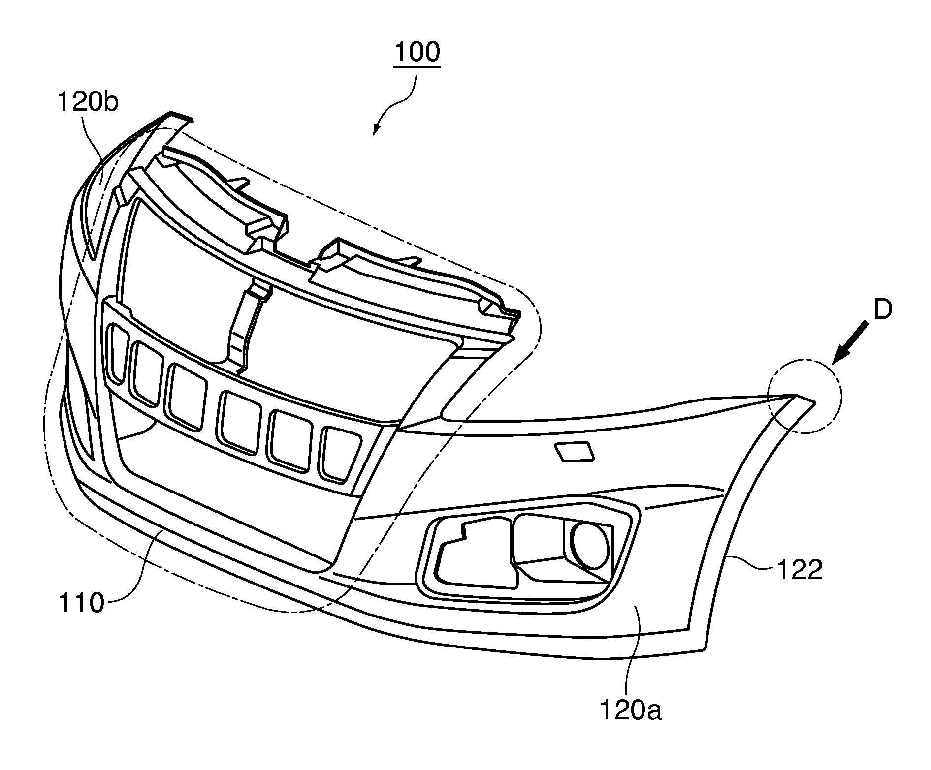
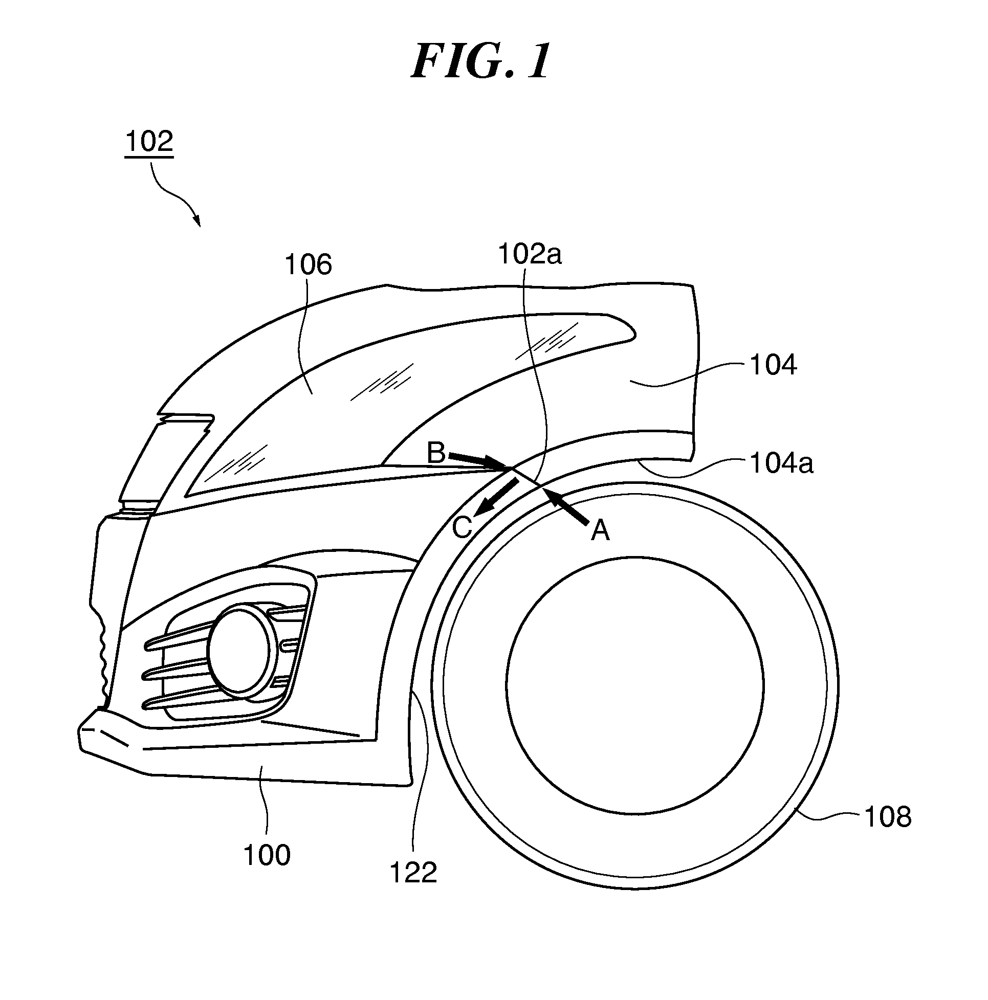
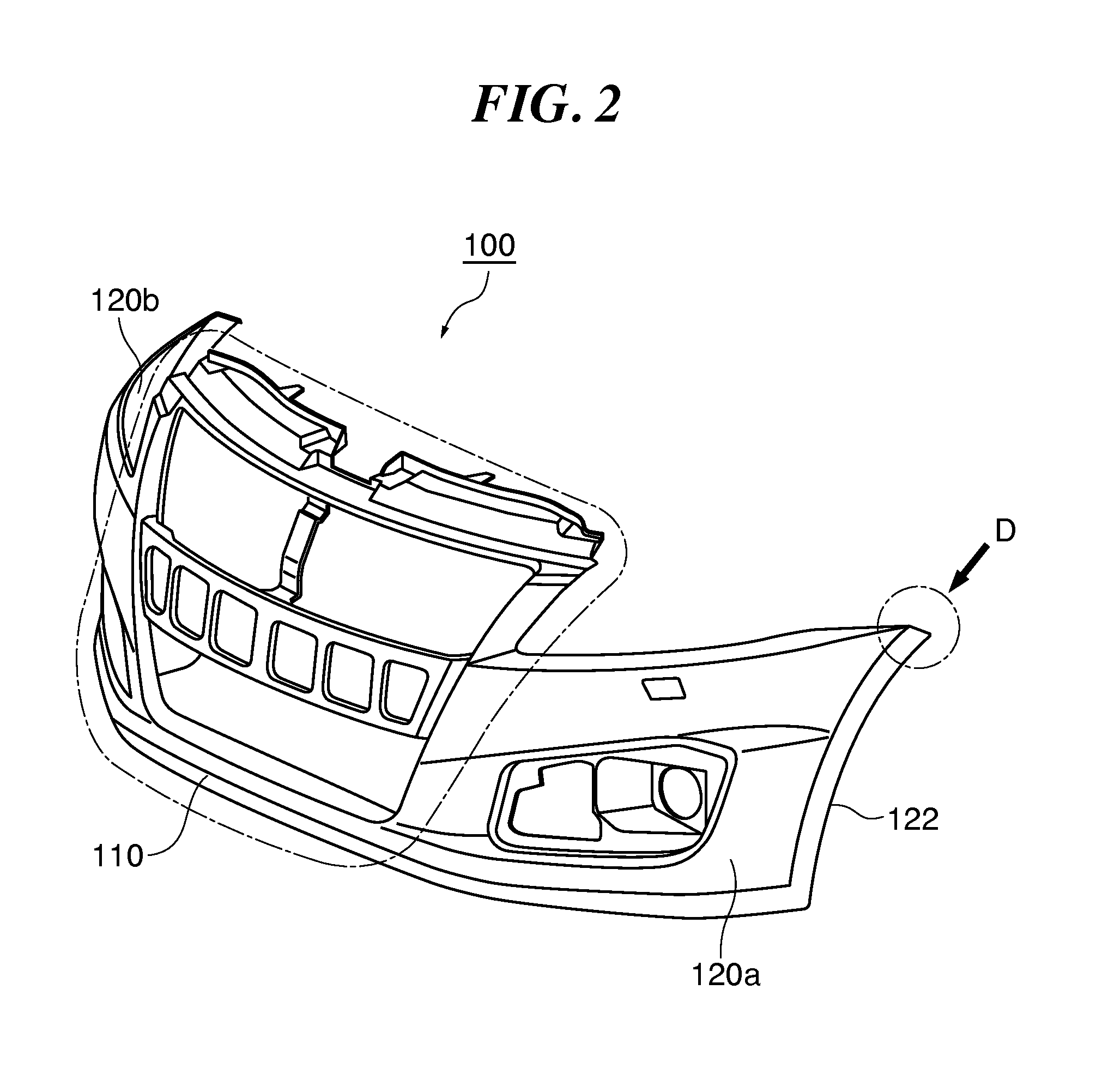
[0027]FIG. 1 is a lateral view of a vehicle body 102 provided with a vehicle bumper according to the present embodiment. As shown in FIG. 1, the vehicle bumper (referred to below as bumper 100) according to this embodiment is a front bumper that constitutes a front face at the fr...


PUM


Abstract

A vehicle bumper is provided that can increase the rigidity while ensuring a superior drainage capability in the vicinity of the location where the bumper is attached to a side face member. A vehicle bumper includes a middle portion extending in vehicle width direction, two lateral portions extending from the two ends of the middle portion towards side face members (front fender panels), an upper flange protruding inward, with respect to a vehicle body, from an upper edge of the lateral portions, an attachment flange that is continuous with the upper flange near an end of the lateral portions and protruding further inside the vehicle body than the upper flange, a long groove formed by a depression in an upper face of the upper flange, at least one rib that partitions the long groove in vehicle width direction into depressions, and water drainage holes formed in the depressions.

Description

CROSS-REFERENCE TO RELATED APPLICATIONS[0001]This application is based upon and claims the benefit of priority from the prior Japanese Patent Application No. 2011-114041, filed on May 20, 2011, the entire contents of which are incorporated herein by reference.BACKGROUND OF THE INVENTION[0002]I. Field of the Invention[0003]The present invention relates to a vehicle bumper constituting a front face or a rear face of a vehicle.[0004]II. Description of the Related Art[0005]Bumpers constituting a front face or a rear face of a vehicle (“front bumper” in case of the front face and “rear bumper” in case of the rear face) are attached to members constituting the side faces of the vehicle (referred to as “side face members” below). For example, the front bumper is attached to front fender panels constituting the side faces of the vehicle front portion, whereas the rear bumper is attached to side body panels constituting the side faces of the vehicle rear portion.[0006]Ordinarily, those porti...

Claims


Application Information

Patent Timeline
Patent Type & Authority Applications(United States)
IPC IPC(8): B60R19/02
CPCB60R2019/247B60R19/24
Inventor MIZOGUCHI, HIROOYAMASHITA, YUSUKE
Owner SUZUKI MOTOR CORP
Why Eureka
Try Eureka