clamp

a technology of clamp and spherical body, which is applied in the field of clamp, can solve the problems of adversely affecting the ability to reduce or remove noise, etc., and achieve the effects of reducing or removing the spherical body, and reducing or removing electromagnetic nois

Inactive Publication Date: 2016-11-24
AUTONETWORKS TECH LTD +2
View PDF15 Cites 6 Cited by
  • Summary
  • Abstract
  • Description
  • Claims
  • Application Information

AI Technical Summary

Benefits of technology

[0008]The magnetic bodies are arranged to face each other around the tubular member and in the main body when the main body is held on the tubular member (in a state where the respective cases are held in contact with each other) by accommodating each magnetic body in each case. Thus, electromagnetic noise from a noise source propagated via the connector and the tubular member can be reduced or removed by the clamp. The clamp reduces or removes the electromagnetic noise and avoids the need to arrange a member near the connector for reducing or removing electromagnetic noise near the connector. Thus, there is no need to enhance the rigidity of the connector or to enlarge the connector.
[0009]The magnetic body is accommodated in each case of the above-described clamp. However, there is a concern that a clearance may be formed between the respective magnetic bodies when the respective cases held in contact with each other and that such a clearance may adversely affect the ability to reduce or remove noise. Further, there is a concern that the magnetic body in each case may be broken by the application of an external impact to the clamp, thereby further adversely affecting the ability to reduce or remove noise. As a measure against this, each magnetic body may be pressed toward the adjacent magnetic body by a repulsive force of each impact absorbing material when the respective cases are held in contact with each other. Thus, the adjacent magnetic bodies are brought closer to each other so that a clearance between the adjacent magnetic bodies can be prevented or suppressed. Therefore, the effect of reducing or removing noise is not degraded by a clearance. Further, the impact absorbing material absorbs impacts that the case receives from outside. Thus, the magnetic body is not likely to break and the effect of reducing or removing noise remains high. More particularly, the impact absorbing material ensures that the effect of reducing or removing noise remains high so that electromagnetic noise can be effectively reduced or removed. As described above, in the above clamp, electromagnetic noise can be effectively reduced or removed without enlarging the connector.
[0010]Each of the cases may have a contact surface to be held in contact with the other case, and each of the magnetic bodies may protrude out from the contact surface in a state where the respective cases are not in contact with each other. According to this configuration, the respective magnetic bodies come into contact with each other before the contact surfaces of the respective cases come into contact with each other when bringing the respective cases into contact with each other. Thus, no clearance is formed between the respective magnetic bodies with the respective cases held in contact with each other. Therefore, the effect of reducing or removing noise by the magnetic bodies remains high.
[0011]One of the case and the magnetic body may include a projection projecting toward the other, and the other of the case and the magnetic body may include a recess facing the projection. Thus, the magnetic body may be held in the case by the convex-concave engagement of the projection and the recess. According to this configuration, the detachment of the magnetic body from the inside of the case due to an external impact or the like can be prevented or suppressed.
[0012]According to the technique disclosed by this specification, it is possible to effectively reduce or remove electromagnetic noise without enlarging a connector.

Problems solved by technology

However, there is a concern that a clearance may be formed between the respective magnetic bodies when the respective cases held in contact with each other and that such a clearance may adversely affect the ability to reduce or remove noise.
Further, there is a concern that the magnetic body in each case may be broken by the application of an external impact to the clamp, thereby further adversely affecting the ability to reduce or remove noise.

Method used


Image

  • clamp
  • clamp
  • clamp

Examples


case 11 , 12

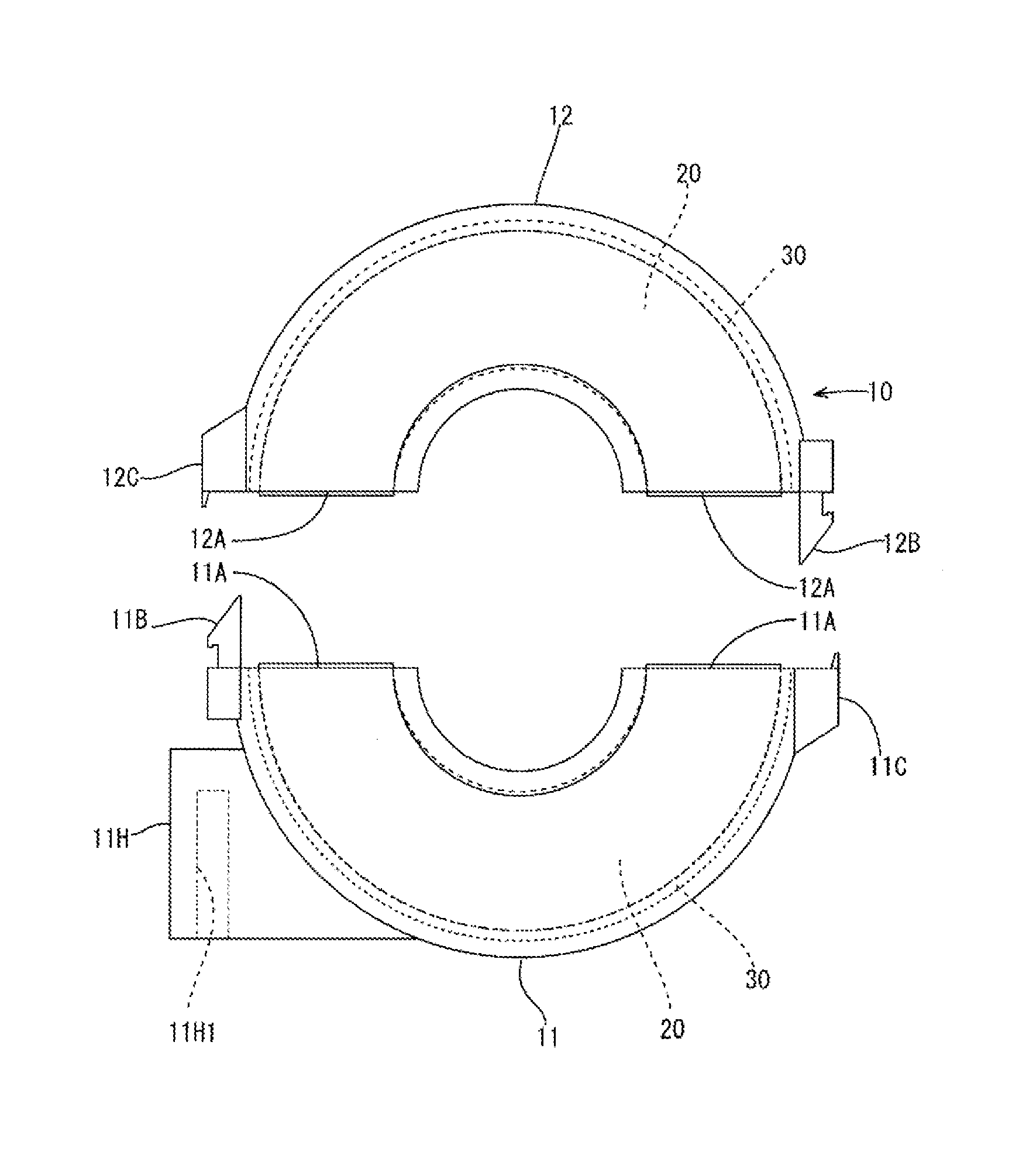
[0022]Each case 11, 12 of the main body 10 is provided, at an outer side of the contact surface 11A, 12A, with an engaging portion 11B, 12B to resiliently engage the other case 12, 11 and an engaged portion 11C, 12C to be engaged with the engaging portion 12B, 11B. These engaging portions 11B, 12B and engaged portions 11C, 12C have a snap-fit structure and are engaged with each other so that the cases 11, 12 are assembled and held while being in contact with each other.

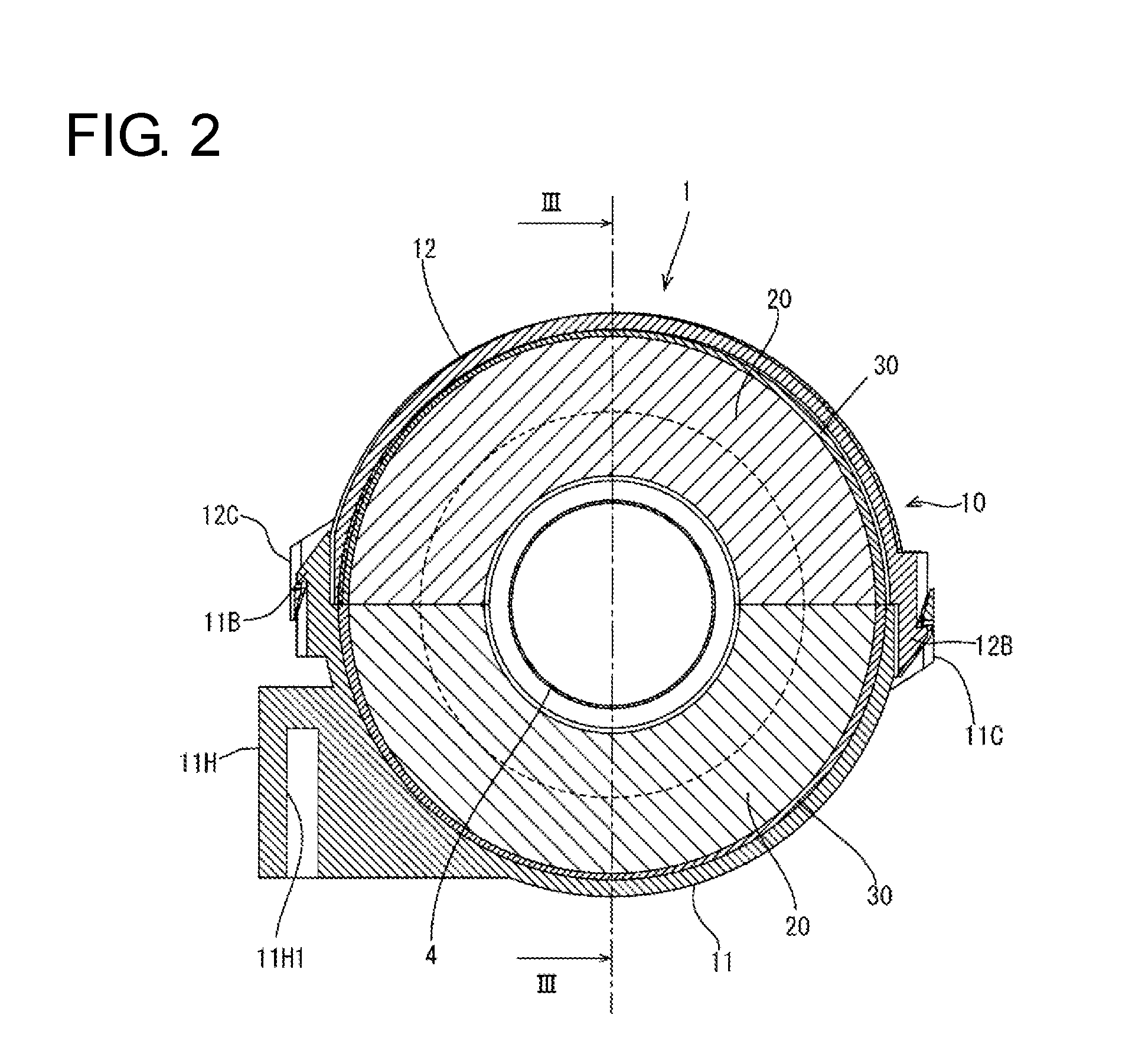
[0023]Further, as shown in FIGS. 2 and 4, the case 11 constituting a lower side of the main body 10 is provided with a fixing portion 11H for fixing the harness clamp 1 onto the above support base. The fixing portion 11H protrudes out from the outer peripheral surface of the case 11. This fixing portion 11H is provided with a fitting groove 11H1 open downward. The harness clamp 1 is fixed onto the support base and the corrugated tube 4 is supported on the support base by fitting this fitting groove 11H1 to an unillust...


PUM

PropertyMeasurementUnit
inner diameteraaaaaaaaaa
magneticaaaaaaaaaa
weightaaaaaaaaaa

Abstract

A harness clamp 1 is to be mounted on an outer peripheral surface of a tubular member covering a wire extending from a connector and includes a hollow tubular main body portion 10 composed of two cases 11, 12 forming an annular opening 10A at each of both ends of the main body portion 10 in a tube axial direction in a state held in contact with each other and held on a corrugated tube 4 by sandwiching the outer peripheral surface of the corrugated tube 4 in the opening 10A at each of the both ends of the main body portion 10 in the tube axial direction, ferrite cores 20 respectively accommodated in the cases 11, 12 and impact absorbing materials 30 respectively arranged to be interposed between the cases 11, 12 and the ferrite cores 20.

Description

BACKGROUND[0001]1. Field of the Invention[0002]This specification relates to a clamp.[0003]2. Description of the Related Art[0004]Conventionally, a connector of a vehicle-mounted device includes a member for reducing electromagnetic noise propagated from the connector to a wire, a cable or the like extending from the connector. For example, Japanese Unexamined Patent Publication No. 2007-5751 discloses a ferrite core holder having a ferrite core accommodated therein. The ferrite core is a magnetic body. This ferrite core holder is mounted on a cable extending from a connector, and the ferrite core can remove electromagnetic noise propagated to the cable extending from the connector.[0005]However, the ferrite core holder disclosed in Japanese Unexamined Patent Publication No. 2007-5751 is mounted in the vicinity of the connector. Thus, the weight of the connector increases due to the self-weight of the ferrite core holder, and the connector must be enlarged to enhance the rigidity of...

Claims


Application Information

Patent Timeline
Patent Type & Authority Applications(United States)
IPC IPC(8): H01F17/06H01F27/02
CPCH01F17/06H01F2017/065H01F27/02
Inventor MUKUNO, JUNICHIHAYASHI, AKIHIROAIZAWA, KATSUHIKOKITAOKA, KENICHI
Owner AUTONETWORKS TECH LTD
Why Eureka
Try Eureka