Device and a method for constructing a flight path in order to reach a destination

a flight path and device technology, applied in the field of aircraft flight management and navigation systems, can solve the problems of not taking into account the volume of noise emitted by the aircraft, affecting the flight experience of the pilot, and suffering sanctions, so as to minimize the noise nuisance and minimize the impact of the pilot's workload in fligh

Inactive Publication Date: 2012-11-22
EUROCOPTER
View PDF9 Cites 33 Cited by
  • Summary
  • Abstract
  • Description
  • Claims
  • Application Information

AI Technical Summary

Benefits of technology

The invention proposes a device that helps plan a flight path and reach a destination with an aircraft while reducing the noise generated by the aircraft and minimizing the impact on the pilot's workload in flight.

Problems solved by technology

The technical problem addressed in this patent text is the need for a system or method to manage the noise emitted by an aircraft in real-time, without interfering with the pilot's ability to safely control the aircraft. This is particularly challenging for helicopters, which require a high level of attention and have limited freedom of action. The goal is to minimize the noise impact on sensitive areas or people while still complying with relevant regulations.

Method used


Image

  • Device and a method for constructing a flight path in order to reach a destination
  • Device and a method for constructing a flight path in order to reach a destination
  • Device and a method for constructing a flight path in order to reach a destination

Examples


first embodiment

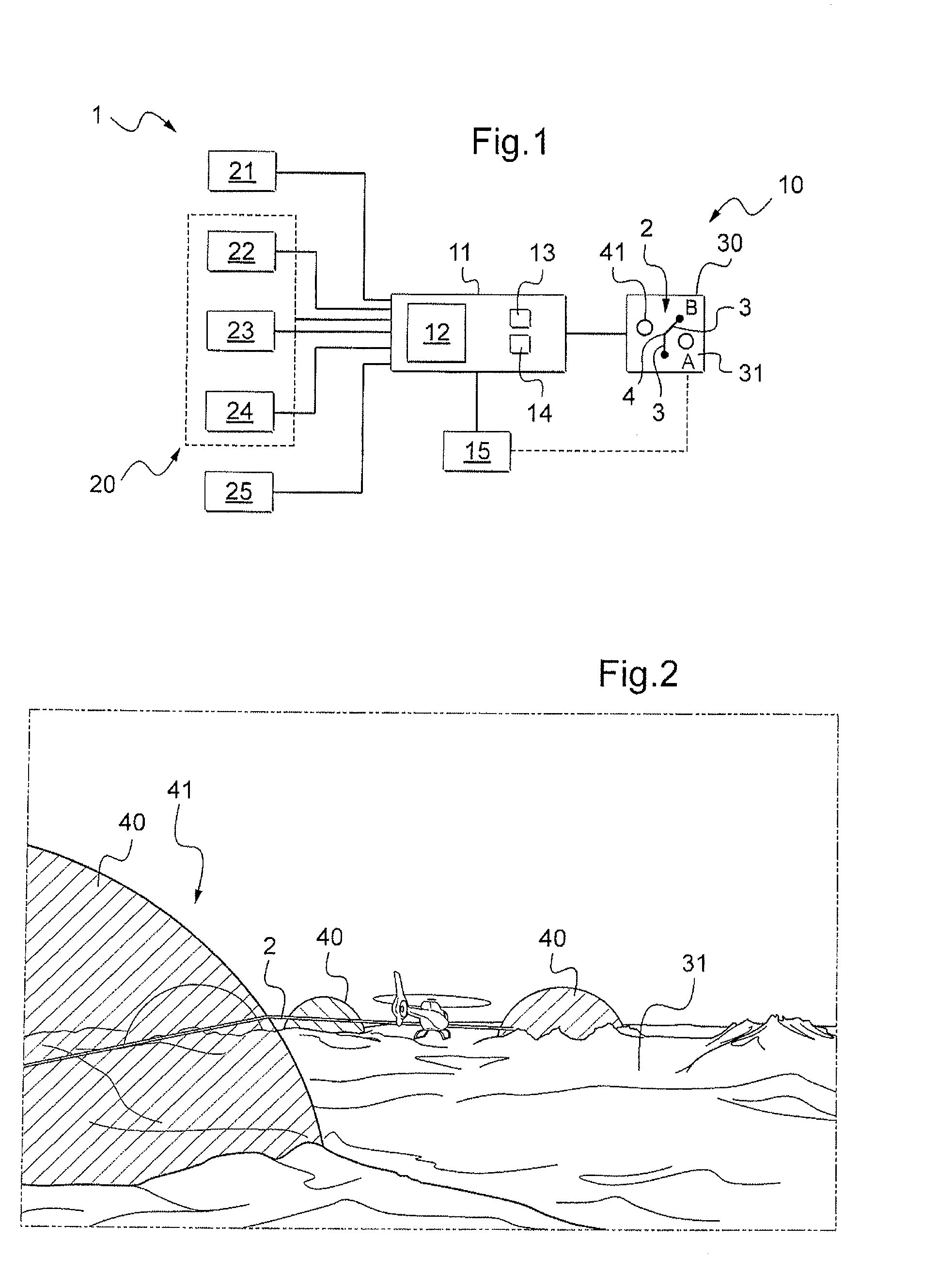
[0106]With reference to FIG. 2, in a first embodiment, the computer causes the first representation 31 and the second representation 41 to be displayed in three dimensions. FIG. 2 shows in particular various volumes to be avoided 40 that are in the form of domes.

second embodiment

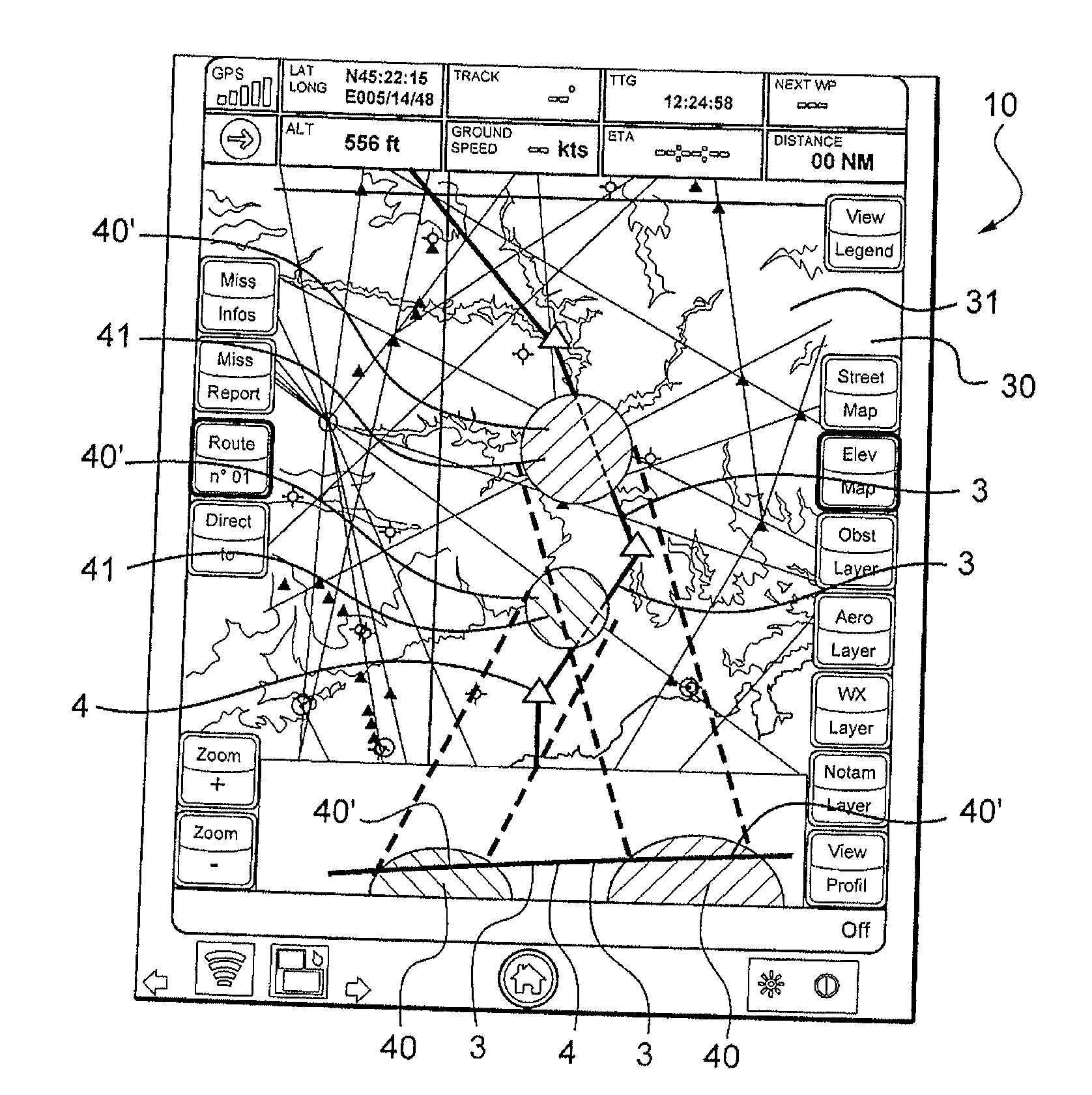
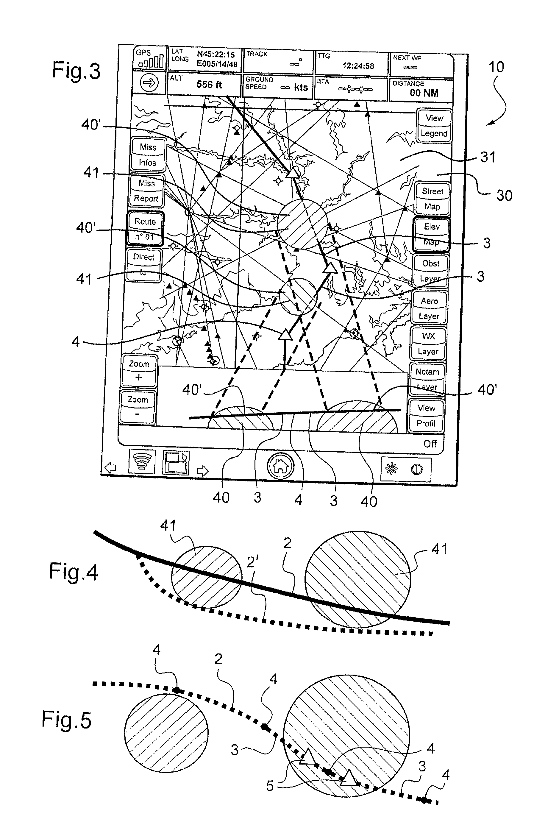
[0107]With reference to FIG. 3, in a second embodiment, the computer causes the first representation 31 and the second representation 41 to be displayed in two dimensions.

[0108]Each segment 3 uniting two waypoints 4 is associated with a flight altitude so it is possible to display no more than a representation of the section 40′ of the volumes to be avoided that are to be found at the flying altitude of the aircraft, i.e. at the altitude of at least one segment 3 of the flight path 2.

[0109]More particularly, it is possible to limit the display to those sections 40′ through which a segment 3 passes that is referred to for convenience as a “risky segment”, like the example shown in FIG. 3.

[0110]Under such circumstances, the computer 11 causes the second representation 41 of said sections 40′ to be displayed in a two-dimensional space.

[0111]Furthermore, with reference to FIG. 5, if a segment of the flight path 2 is a risky segment passing through a volume that is to be avoided, informa...


PUM


Abstract

A device (10) for defining a flight path (2) enabling an aircraft (1) to reach a destination (B), said device (10) including a digital terrain model (21) and a display screen (30), and being provided with generator means (15) for generating a flight path (2) including at least one flight segment (3) associated with a flying altitude. The device (10) includes a digital noise database (20) having volumes that are to be avoided, said device (10) having a computer (11) with a main memory (13) containing instructions for displaying on said display screen (30) and as an overlay on a first representation (31) of said terrain as provided by said digital terrain model (21): a second representation (41) of said volumes to be avoided; and a flight path (2) that has been generated by using said generator means (15).

Description


Claims


Application Information

Patent Timeline
Owner EUROCOPTER
Why Eureka
Try Eureka