Dynamic anomalous pixel detection and correction

a dynamic anomalous and pixel detection technology, applied in the direction of color signal processing circuits, color television details, television systems, etc., can solve the problems of defective pixels, unsatisfactory processing of image sensors, undesirable to the end user, etc., to achieve minimal processing load and/or video frame rate, simple statistical routine, and simple software algorithm

Inactive Publication Date: 2006-03-07
LOGITECH EURO SA
View PDF67 Cites 86 Cited by
  • Summary
  • Abstract
  • Description
  • Claims
  • Application Information

AI Technical Summary

Benefits of technology

[0008]The software algorithm is intentionally kept very simple so that the processor load and / or the video frame rate is minimally affected. First, the software algorithm is kept simple because it only performs three functions, namely the detection, correction and statistics functions. The statistics routine is kept simple because only position information and frequency of occurrence of anomalous pixels are tracked. Second, the software algorithm is kept simple so as to have a minimal impact on the rate at which data is transferred to the host, so that while a frame is being scanned for defective pixels, subsequent frames are not held up. The maximum impact of the software algorithm is to at worst reduce the video data transfer rate from 10 frames per second (fps) to 9 fps. Third, the software algorithm is kept simple such that the host processor's load is not increased by more 1% when executing the algorithm. The anomalous pixels are detected in one frame and the corrections are later instituted on subsequent frames as they are read off the image sensor.
[0009]Dynamic defective pixel detection and correction is important for a number of reasons. First and foremost, image quality can be significantly improved and second, sensor cost can be substantially decreased by increasing the yield or usability of otherwise scrap sensors. Dynamic intelligent host software application based anomalous pixel detection and correction has several additional cost and quality benefits over the traditional hardware-based approaches. First, it reduces manufacturing cost by not having to add and program memory during product assembly and test. Second, it allows for further reductions in cost by not including the correction logic in the video processing ASIC. Finally, it allows for the correction of raw pixel data taken from sensor photosites which may become defective over time and with operating environment changes.

Problems solved by technology

The processes used to produce these image sensors though highly advanced are not perfect.
This can result in a displayed image having a dark or black dot, bright white dot or incorrect color dot, all of which are unwanted and are undesirable to the end user.
The defective pixels are produced when or after the image sensor array is manufactured.
The disadvantage of such approaches is the need to incorporate and program memory devices during product assembly and testing which add costs and delays.
Additionally, the hardware device costs will also increase due to the need to add the correcting circuitry or logic to the video processing application specific integrated circuit (ASIC).
These methods typically rely on rather sophisticated and expensive systems and computer software to detect and correct bad pixels.
Besides requiring user input, such approaches are also expensive, tedious and very time consuming.

Method used


Image

  • Dynamic anomalous pixel detection and correction
  • Dynamic anomalous pixel detection and correction
  • Dynamic anomalous pixel detection and correction

Examples


Embodiment Construction

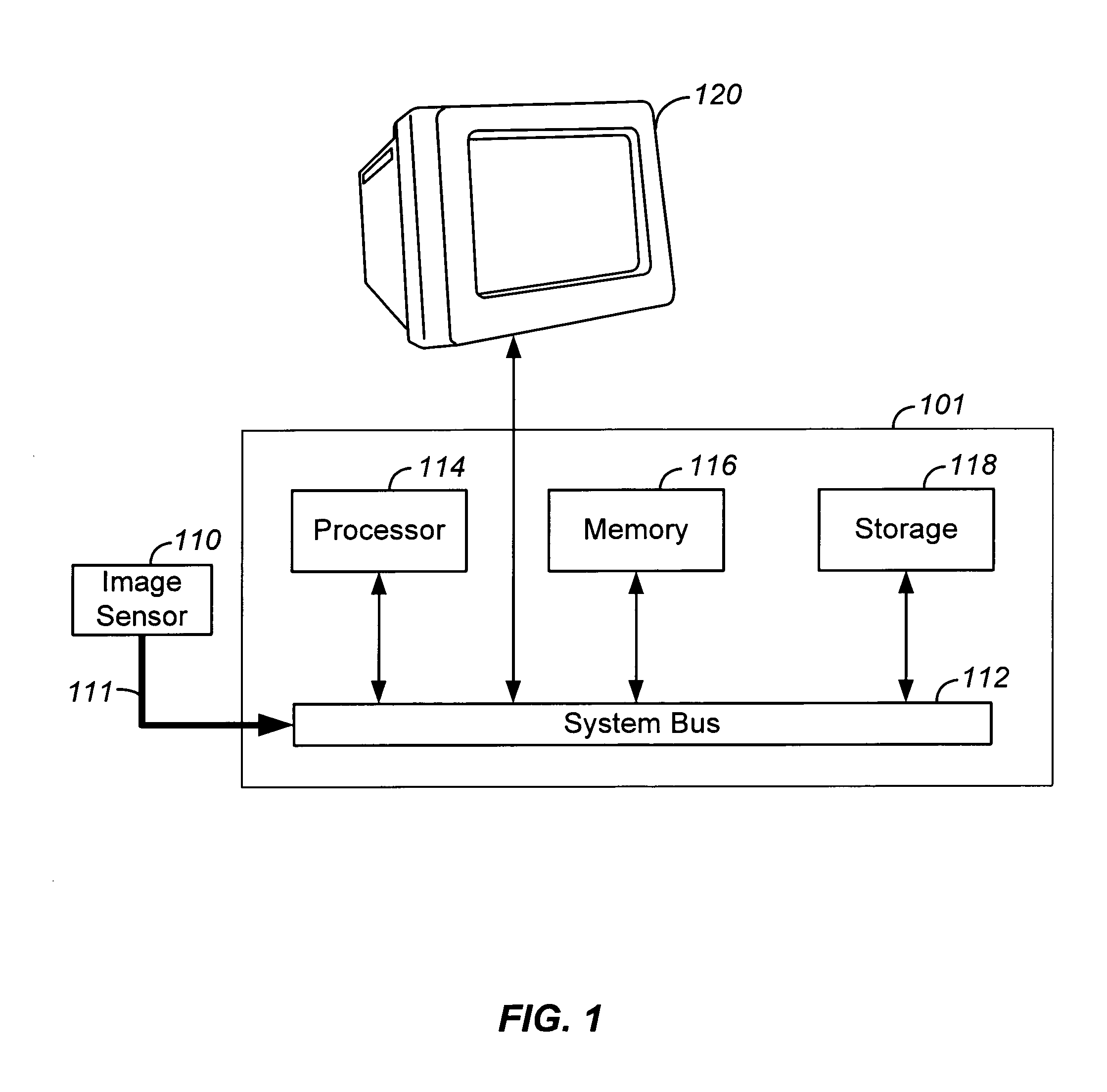
[0012]FIG. 1 shows an embodiment of the present invention which uses software algorithms running on an intelligent host processor 114 to dynamically correct defective or anomalous pixels. In one embodiment, the intelligent host is a server or a PC. The system includes an image sensor 110 to capture an image, an intelligent host 101 having a processor 114 to execute the computer program stored in storage 118, and a system bus 112 to facilitate device communications. The image sensor array can either be a charge-coupled device (CCD) or a complimentary metal oxide semiconductor (CMOS) image sensor array, which are typically parts of a video or still digital camera. The image sensor 110 communicates with the host 101 via an external bus 111, which can be a universal serial bus (USB) or a parallel port. Upon transfer of appropriate calls between the processor 114 and the image sensor 110, the computer program is loaded into memory 116.

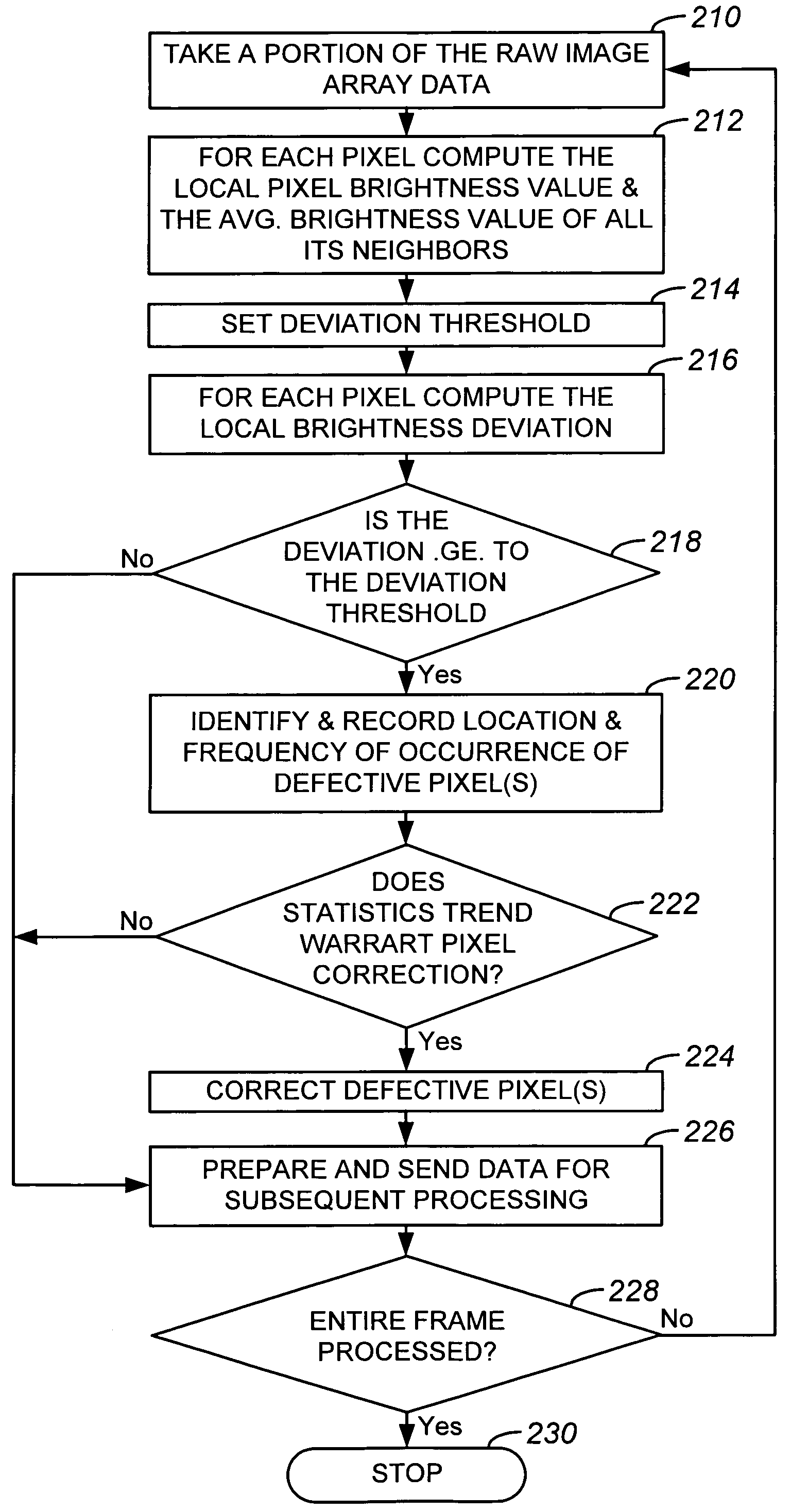
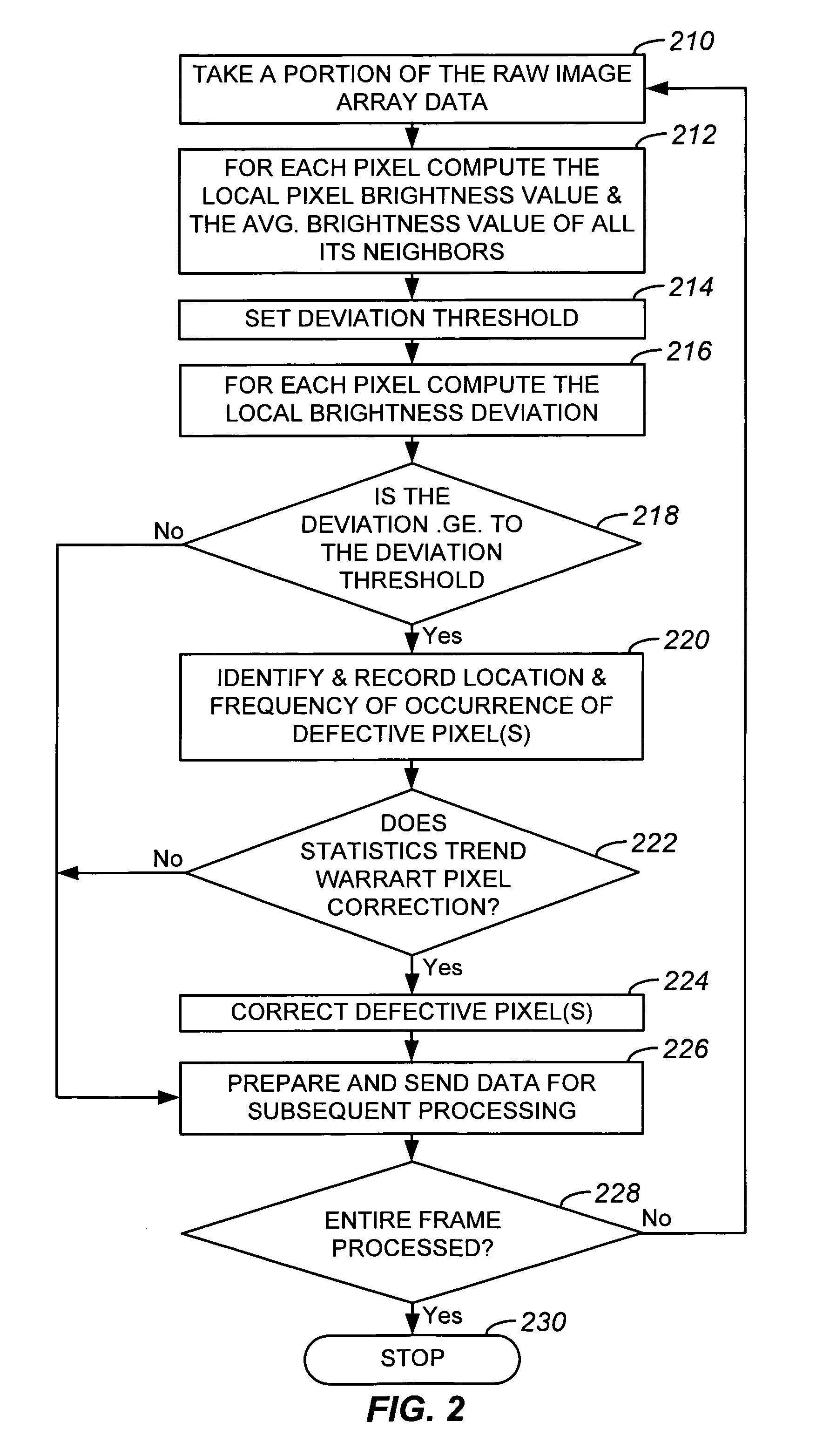
[0013]The system works by reading off or scanning the...


PUM


Abstract

A method and a system for dynamically detecting and correcting anomalous pixels in the raw data taken from an image sensor array such as a CCD or a CMOS sensor array, thus allowing the use of dumb cameras to capture digital images for subsequent use by an intelligent host—such as being displayed on a computer monitor. This invention uses software algorithms running on an intelligent host processor to dynamically correct the anomalous pixels in the raw data taken from an image sensor array typical of those in a digital still or a video camera. Using the combination of a dumb camera which provides raw data to an intelligent host, which does all the subsequent image processing, the system works by scanning an image frame for pixels that vary more than a specified amount in their brightness value from their neighboring pixels and designating those as defective pixels. The location and frequency of the photosites sending the defective pixels are stored in a statistical database in the computer's memory. The brightness value of a defective pixel is then replaced by a local brightness value obtained from the defective pixel's neighboring pixels. The process includes video subsampling, meaning that the defective pixel detection is carried out and repeated at a pre-specified frame rate to ensure optimum detection and correction at a minimal level of scanning. A statistical database is kept so that truly anomalous pixels can over time be distinguished from false detection of true anomalies in the target image, lighting or other environmentally induced anomalies.

Description

BACKGROUND OF THE INVENTION[0001]The present invention relates to digital still or video cameras using a solid state image pickup device and more particularly to methods and systems used to detect and correct defective pixels obtained from a solid state image pickup device.[0002]The foundation of digital imaging is the image sensor. Just as in a traditional camera, light enters a digital still or video camera through a lens controlled by a shutter. When the shutter opens, rather than exposing film, the digital camera collects light on an image sensor—a solid state electronic device. Image sensors contain a grid of microscopic photosites or pixels. In a camera, each photosite on the image sensor may represents one pixel of a digitized image. Two types of image sensors that are quite prevalent in the digital imaging field are the charge-coupled device (CCD) and the complimentary metal oxide semiconductor (CMOS) image sensor arrays. These image sensors may contain anywhere from a few h...

Claims


Application Information

Patent Timeline
Patent Type & Authority Patents(United States)
IPC IPC(8): H04N9/64H04N5/217H04N5/232H04N5/367H04N7/26H04N21/4143
CPCH04N5/2173H04N5/232H04N19/00H04N21/4143H04N5/3675H04N25/60H04N23/661H04N25/683
Inventor SANCHEZ, GEORGEBILLERBECK, BRYEDZIMMERMAN, REMY
Owner LOGITECH EURO SA
Why Eureka
Try Eureka