Magnetic energy power device

A magnetic energy power, power unit technology, applied in electromechanical devices, magnetic circuit rotating parts, magnetic circuit and other directions, can solve problems such as the inability to achieve stable rotor operation

Inactive Publication Date: 2021-09-14
伍康旺
View PDF0 Cites 0 Cited by
  • Summary
  • Abstract
  • Description
  • Claims
  • Application Information

AI Technical Summary

Problems solved by technology

The magnetic energy power device can be used as the auxiliary power mechanism of the existing motor to save the electric energy when the motor is driven, but th

Method used


Image

  • Magnetic energy power device
  • Magnetic energy power device
  • Magnetic energy power device

Examples


Embodiment approach 1

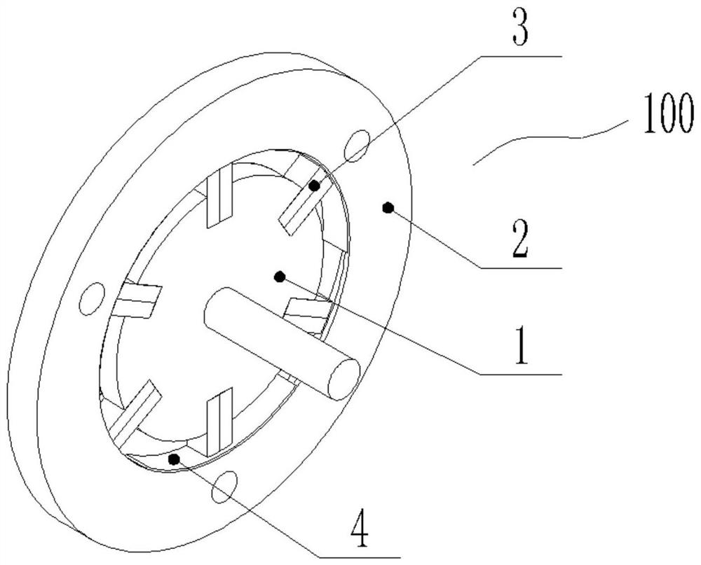
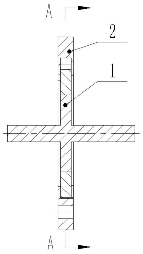
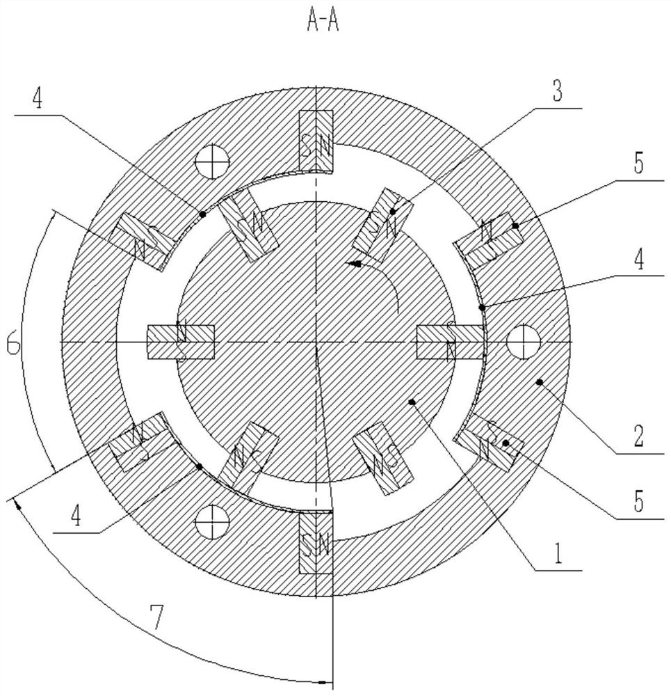
[0061] Implementation mode one: if image 3 As shown, the first rotating body 1 is a rotor, the second rotating body 2 is a stator, and the first rotating body 1 is located inside the second rotating body 2 . The first rotating body 1 is a disk or a ring, and the second rotating body 2 is a ring. The first permanent magnet 3 is fixed on the outer wall of the first rotating body 1 , and the second permanent magnet 5 is fixed on the inner wall of the second rotating body 2 . The first rotating body 1 is arranged coaxially with the rotating shaft and is fixedly connected.

Embodiment approach 2

[0062] Implementation mode two: if Figure 4 As shown, the first rotating body 1 is a rotor, the second rotating body 2 is a stator, and the first rotating body 1 is located outside the second rotating body 2 . The first rotating body 1 is a ring, and the second rotating body 2 is a disc or a ring. The first permanent magnet 3 is fixed on the inner wall of the first rotating body 1 , and the second permanent magnet 5 is fixed on the outer wall of the second rotating body 2 . The first rotating body 1 is arranged coaxially with the rotating shaft and is fixedly connected.

Embodiment approach 3

[0063] Implementation mode three: if Figure 5 As shown, the first rotating body 1 is a stator, the second rotating body 2 is a rotor, and the first rotating body 1 is located inside the second rotating body 2 . The first rotating body 1 is a disk or a ring, and the second rotating body 2 is a ring. The first permanent magnet 3 is fixed on the outer wall of the first rotating body 1 , and the second permanent magnet 5 is fixed on the inner wall of the second rotating body 2 . The second rotating body 2 is arranged coaxially with the rotating shaft and is fixedly connected.


PUM


Abstract

The invention relates to a magnetic energy power device which is characterized in that at least one first permanent magnet is fixed on the side wall, facing a second rotating body, of a first rotating body at intervals in the circumferential direction, the magnetic pole directions of the at least two first permanent magnets are the same, at least one second permanent magnet group is fixed on the side wall, facing the first rotating body, of the second rotating body at intervals in the circumferential direction, each second permanent magnet group comprises two second permanent magnets of which the same magnetic poles are oppositely arranged at intervals, the second permanent magnets are called as magnetic shielding sections, and the other positions are driving sections. The beneficial effects are that when the first permanent magnet passes through the driving section, the magnetic poles at the two ends of the first permanent magnet are respectively subjected to the suction force and the repulsive force of the two second permanent magnets in the driving section, so that the first rotary body or the second rotary body rotates. The magnetic circuit of the driving section forms a driving process in a single direction, and the rotor is driven to rotate to do work.

Description

technical field [0001] The invention relates to a power mechanism using magnetic energy as a power source, in particular to a magnetic energy power device. Background technique [0002] Because permanent magnets have the ability to work naturally, many people at home and abroad have been exploring power devices that use magnetic energy as an energy source in the past century. Especially when rare earth elements are used, the magnetic energy product of permanent magnets has been greatly improved. Finally, providing kinetic energy through the magnetic energy of permanent magnets has great potential. The magnetic power device can be used as the auxiliary power mechanism of the existing motor to save the electric energy when the motor is driven, but the problem of the arrangement angle of the magnet in the magnetic effect has not been effectively solved, and the smooth operation of the rotor cannot be realized. Contents of the invention [0003] The technical problem to be so...

Claims


Application Information

Patent Timeline
IPC IPC(8): H02K53/00H02K1/27
CPCH02K53/00H02K1/2746H02K1/2786
Inventor 苏铮伍海培伍康旺张德仰伍长序伍洲朱万君李祥明
Owner 伍康旺
Why Eureka
Try Eureka