Wall stud mounting bracket for securing and positioning flexible conduit and cable

a technology for mounting brackets and flexible conduits, which is applied in the direction of machine supports, building repairs, other domestic objects, etc., can solve the problems of shipping and inventory problems for customers, the difficulty of mounting the strut in any other fashion, and the increase in the time required to install the electrical box and fasten the strut to the stud

Active Publication Date: 2012-11-29
ILLINOIS TOOL WORKS INC
View PDF7 Cites 30 Cited by
  • Summary
  • Abstract
  • Description
  • Claims
  • Application Information

AI Technical Summary

Problems solved by technology

Unfortunately electrical boxes come in two separate depths which require different spacing or set back of the strut from the edges of the studs for each box depth size.
Pre-bent flanges for one type of stud mounting make it difficult if not impossible to mount the strut in any other fashion.
This problem has created shipping and inventory problems for customers which required field selection of the right strut for the right box, and for the right stud mounting application.
Often times the installer would lose his or her grip on the strut and the strut would move or fall, resulting in possible misalignmen...

Method used


Image

  • Wall stud mounting bracket for securing and positioning flexible conduit and cable
  • Wall stud mounting bracket for securing and positioning flexible conduit and cable
  • Wall stud mounting bracket for securing and positioning flexible conduit and cable

Examples


Embodiment Construction

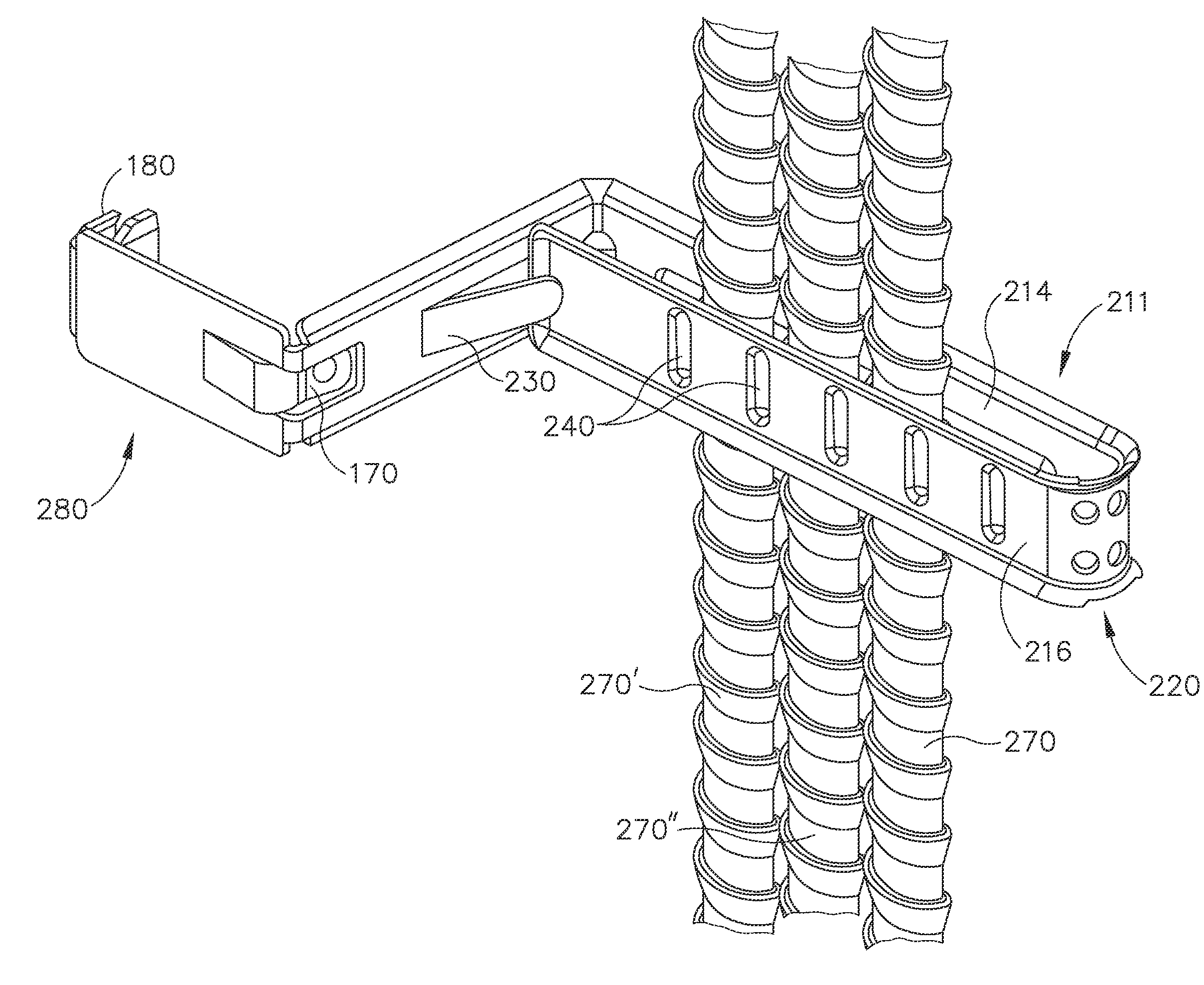
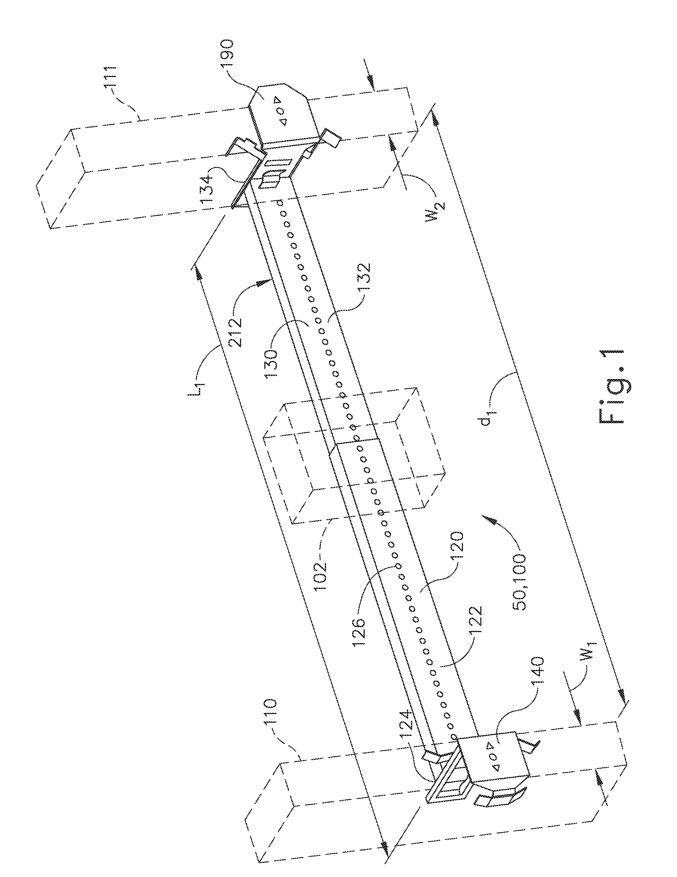
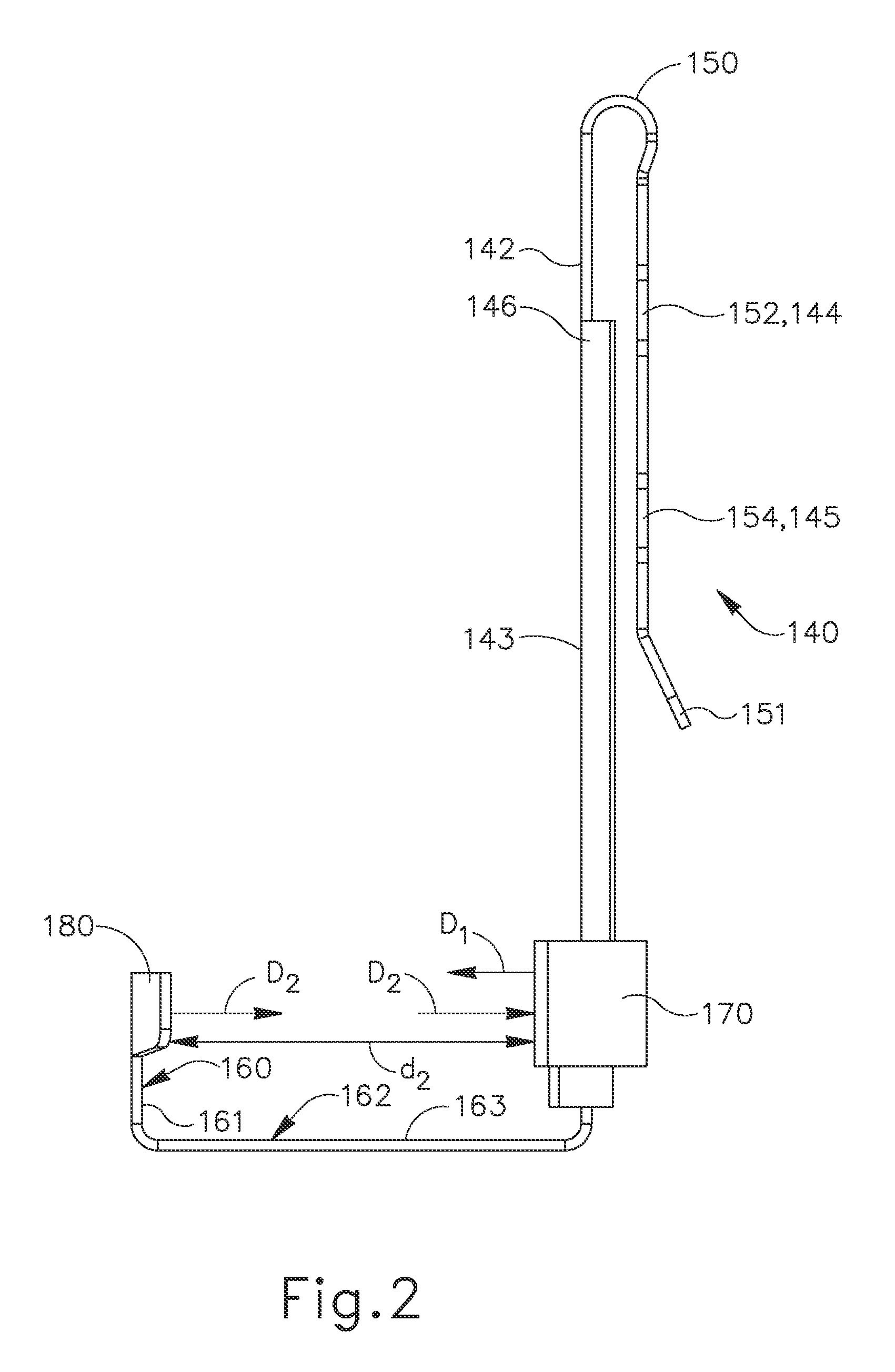
[0054]Methods and devices consistent with the present invention overcome the disadvantages of conventional electrical box support assemblies by using a u-shaped engaging tab having a pair of opposing engagement members and by having a compressible member extending from one of the opposing engagement members and towards another of the opposing engagement members, it is possible to readily mount and easily secure the electrical box support assembly of the present invention to any interior or exterior surface of a metal stud, or the exterior of a wood stud, preferably without the use of additional fasteners.

[0055]Additional methods and device consistent with the present invention overcome disadvantages of conventional support assemblies which use a wall stud bracket fastened to a wall stud to support a structural member by using an engaging tab for connecting the structural member with the wall stud. The engaging tab includes a pair of engagement members which engage non-mounting faces...


PUM


Abstract

A support assembly connected with a stud for securing and guiding conduit and/or cable is provided. The support assembly includes, but is not limited to, a securing arm for securing and guiding the conduit and/or cable and an engaging tab coupled with an end of the securing arm. The engaging tab includes a first engagement member facing a second engagement member, a side engagement member connecting the first and second engagement members together, and a first compressible member extending in a first direction D1 either from the first engagement member towards the second engagement member or from the second engagement member towards the first engagement member. The first compressible member is compressible in a second direction D2 opposite that of the first direction D1.

Description

CROSS-REFERENCES TO RELATED APPLICATIONS[0001]The Present application is a continuation-in-part of U.S. patent application Ser. No. 13 / 117,837 entitled “ELECTRICAL BOX SUPPORT ASSEMBLY” and filed on May 27, 2011 with the United States Patent and Trademark Office, the contents of which are hereby incorporated by reference in their entirety to the extent permitted by law.BACKGROUND OF THE INVENTION[0002]Certain applications require fastening a support assembly to a wall stud. The support assembly may be used for various purposes, such as to hold an electrical box or to secure and guide cables within a studded wall. Preferably the support assembly includes a wall stud bracket for fastening the support assembly to a wall stud. For example, some applications require using a support assembly which includes a two part telescoping strut for supporting an electrical box or similar device in a studded wall. Preferably, the support assembly includes a pair of wall stud brackets connected with ...

Claims


Application Information

Patent Timeline
IPC IPC(8): F16L3/01E04B1/38
CPCH02G3/32F16L3/24F16L3/243Y10S248/906
Inventor SIDDIQUI, ASIMCARINGELLA, ANTHONYCOLANGELO, TOMMCMATH, JUSTIN
Owner ILLINOIS TOOL WORKS INC
Why Eureka
Try Eureka