Transformer and priming circuit therefor

a transformer and priming circuit technology, applied in the field of transformers, can solve the problems of transformers having a characteristic ‘humming’ noise which may be undesirable, inefficient and low-frequency transformers,

Inactive Publication Date: 2012-11-29
AUCKLAND UNISERVICES LTD
View PDF4 Cites 19 Cited by
  • Summary
  • Abstract
  • Description
  • Claims
  • Application Information

AI Technical Summary

Benefits of technology

[0010]It is an object of the invention to provide an improved transformer, particularly a transformer using electrostatic tran...

Problems solved by technology

Electromagnetic transformers are known to be inefficient at certain, especially low, frequencies.
They typically require metallic components and create magnetic ‘noise’, neither of which are desirable in some applications.
Transformers have a characteristic ‘humming’ noise which may be undesirable.
Piezoelectric transformers are known ...

Method used


Image

  • Transformer and priming circuit therefor
  • Transformer and priming circuit therefor
  • Transformer and priming circuit therefor

Examples


Embodiment Construction

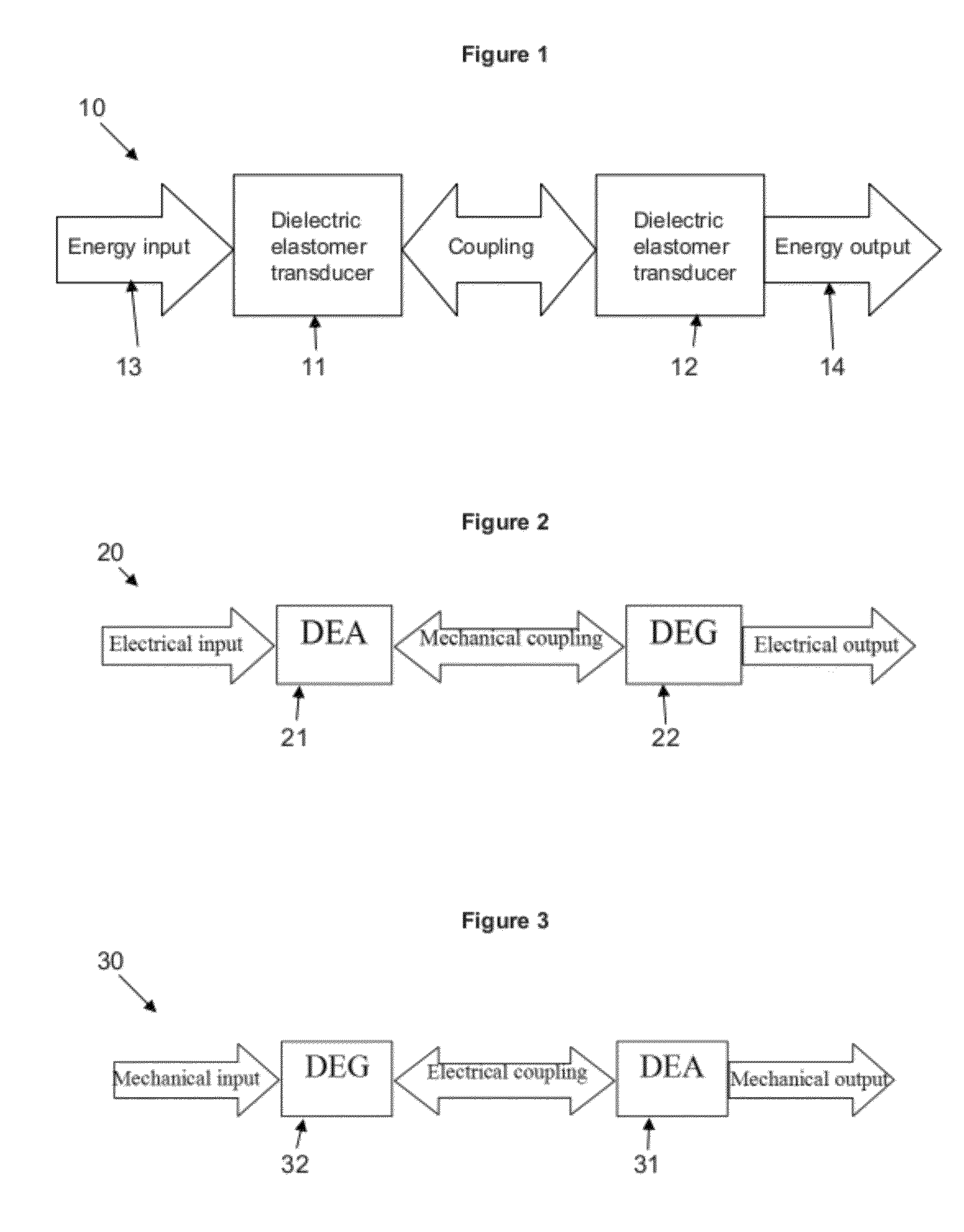
[0121]In broad terms, the invention provides a transformer having at least one electrostatic transducer. Energy is provided to the transformer in a first form (namely by deformation of or applying a voltage across at least one body). Through selection of couplings (mechanical and / or electrical) between the bodies and the properties and numbers thereof, a desired transformation can be achieved. Preferably, the transformation results in the output of energy in the first form but having a different property.

[0122]In the following description, transformers according to the invention will be described. By way of example, preferred embodiments are described which include two dielectric elastomer transducers; typically an actuator and generator. The invention also encompasses transformers including a dielectric elastomer generator and more generally any actuator (i.e., including non-dielectric elastomer-based actuators). The actuator may be a dielectric elastomer actuator or another type o...


PUM


Abstract

The invention relates to transformers. More particularly, the invention relates to transformers using (preferably electrostatic and more preferably dielectric elastomer) transducers such as generators and actuators. The invention further provides a priming circuit therefor.

Description

FIELD OF INVENTION[0001]The invention relates to transformers. More particularly, the invention relates to transformers using (preferably electrostatic and more preferably dielectric elastomer) transducers such as generators and actuators. The invention further provides a priming circuit therefor.BACKGROUND TO THE INVENTION[0002]An electro-active polymer (EAP) is a soft actuator that can generate high stress and large strain. A dielectric elastomer actuator (DEA) is an EAP which uses a dielectric elastomer film or membrane with a flexible electrode attached to each face. Application of a voltage difference across the electrodes generates Maxwell stress. The two electrodes are urged together by electrostatic attraction of free charges on the electrodes, causing the thickness of the membrane to decrease and the surface area of the faces to increase. This deformation is further caused by electrostatic repulsion of like charges on each individual face. Thus, application of a voltage to ...

Claims


Application Information

Patent Timeline
IPC IPC(8): H02K57/00
CPCH01L41/044H02N2/181H01L41/193H01L41/107H10N30/40H10N30/857
Inventor ANDERSON, IAIN ALEXANDERMCKAY, THOMAS GREGORYO'BRIEN, BENJAMIN MARCCALIUS, EMILIO PATRICIO
Owner AUCKLAND UNISERVICES LTD
Why Eureka
Try Eureka