Dental imaging apparatus

Active Publication Date: 2012-11-29
PLANMECA
View PDF2 Cites 12 Cited by
  • Summary
  • Abstract
  • Description
  • Claims
  • Application Information

AI Technical Summary

Benefits of technology

[0007]The invention introduces a new arrangement for versatile modelling of the patient's cranial anatomy. The invention enables, among others, using existing imagin

Problems solved by technology

Among others, the need for acquiring a separate device for a particular imaging purpose has been limiting utilisation of facial texture models in the dental field.
Acquiring a separate device is not only a question of costs but also of space, as each device always requires a space to be installed and/or stored in and/or where it can be used.
On the other hand, each separate imaging always

Method used


Image

  • Dental imaging apparatus
  • Dental imaging apparatus
  • Dental imaging apparatus

Examples


Example

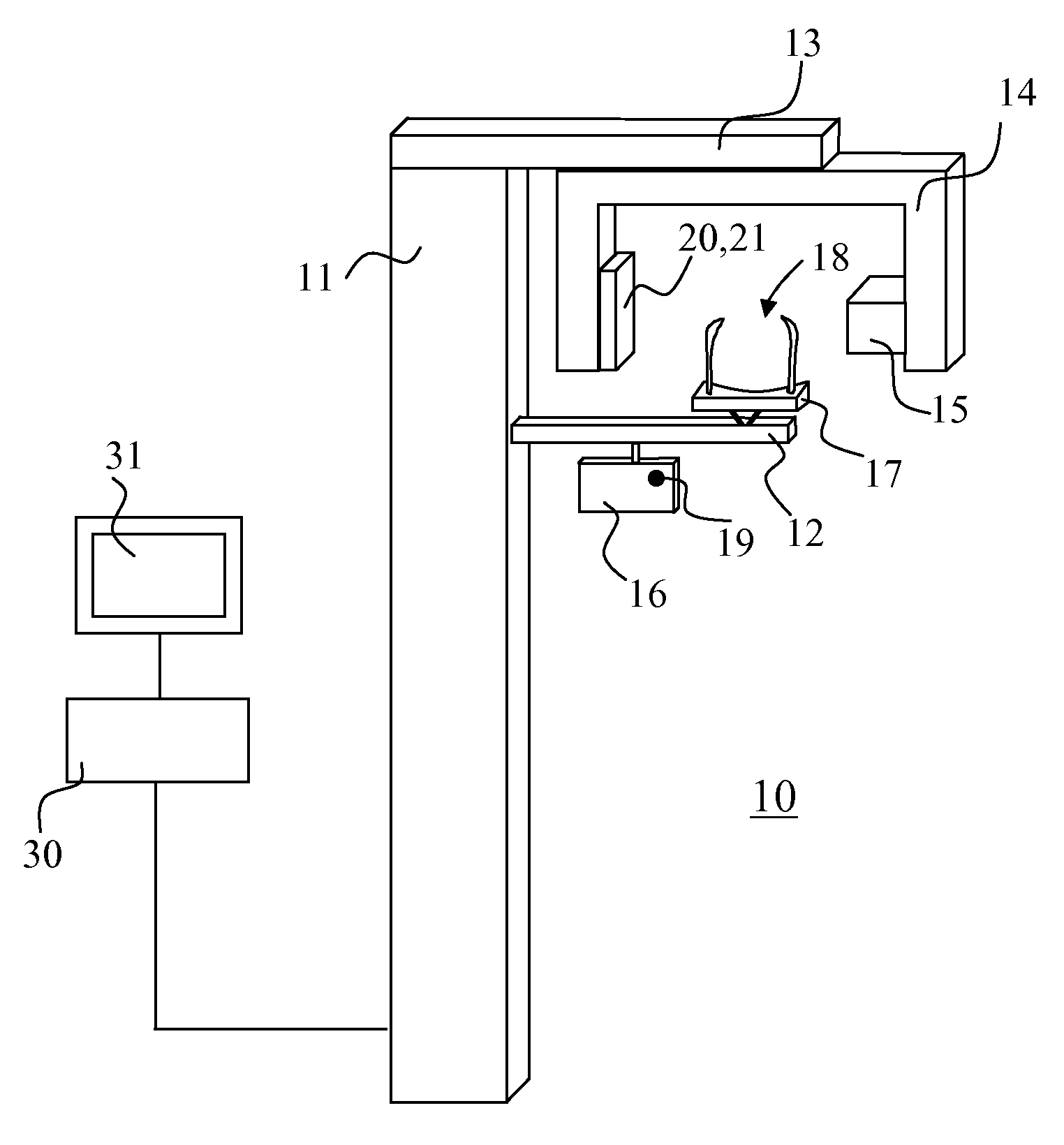
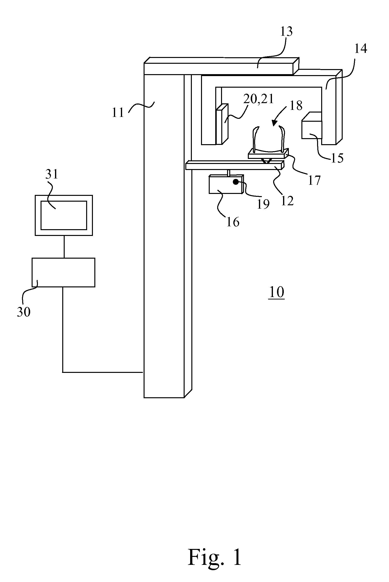
[0015]FIG. 1 shows one imaging apparatus according to the invention. The apparatus includes a vertical support construction (11) from which horizontally extends an arm (12) supporting a patient support means and an arm part (13) which supports a structure supporting imaging means of the apparatus, an arm part (14). The arm part supporting the imaging means (14) may be arranged rotatable. To the arm part supporting the imaging means (14) are arranged at a distance from each other an x-ray source (15) and a receiver of x-ray image information (21), which are located at the apparatus with respect to a patient support means (17) such that an imaging station (18) is created to the apparatus which is located between the x-ray source (15) and the receiver means of x-ray image information (21) such that a beam produced by the x-ray source (15) can be directed to go through said imaging station (18) towards the receiver means of x-ray image information (21). The apparatus includes control me...


PUM


Abstract

The invention relates to a dental imaging apparatus which includes an x-ray imaging means and at least one colour camera for photographing the face of a patient positioned at the imaging station of the apparatus, which at least one colour camera is arranged to image the patient's face positioned at the patient support station from different directions, and means arranged into functional connection with said at least one colour camera for creating a virtual three-dimensional texture model of the patient's face.

Description

FIELD OF INVENTION[0001]The invention relates to a dental imaging apparatus according to the preamble of claim 1.BACKGROUND OF INVENTION[0002]The history of medical x-ray imaging originates approximately to the time of inventing x-radiation. For more advanced ways of imaging, e.g. the development of panoramic x-ray imaging in the dental field started for over a half century ago. The development of digital imaging especially in the 1990s brought digital x-ray imaging devices also to dental practices. The latest development step in the dental field has been the generalisation of the cone-beam computed tomography apparatus designed for three-dimensional imaging of skeletal structures of the cranial area. Concerning new possibilities offered by them, worth mentioning is e.g. applications related to implant attachment and other treatment planning.[0003]Along with the development of cameras and information technology, such as that of computing power of computers, it has become possible to...

Claims


Application Information

Patent Timeline
IPC IPC(8): A61B6/14A61B6/03G01N23/04
CPCA61B5/0064A61B5/1079A61B6/032A61B6/4417A61B6/5247G06T17/00A61B6/14G06T15/04G06T17/20G06T2210/41G06T2215/16
Inventor KOIVISTO, JUHANYHOLM, KUSTAADE GODZINSKY, CHRISTIAN
Owner PLANMECA
Why Eureka
Try Eureka