System and method for operating a flow battery system at an elevated temperature

a flow battery and elevated temperature technology, applied in the field of flow battery systems, can solve problems such as limited concentration

Active Publication Date: 2012-12-20
RAYTHEON TECH CORP
View PDF8 Cites 32 Cited by
  • Summary
  • Abstract
  • Description
  • Claims
  • Application Information

AI Technical Summary

Problems solved by technology

However, the concentrations are limited by the solubility of the vanadium salts in the solvent electrolyte, which is typically an aqueous acid such as sulfuric acid.

Method used


Image

  • System and method for operating a flow battery system at an elevated temperature
  • System and method for operating a flow battery system at an elevated temperature
  • System and method for operating a flow battery system at an elevated temperature

Examples


Embodiment Construction

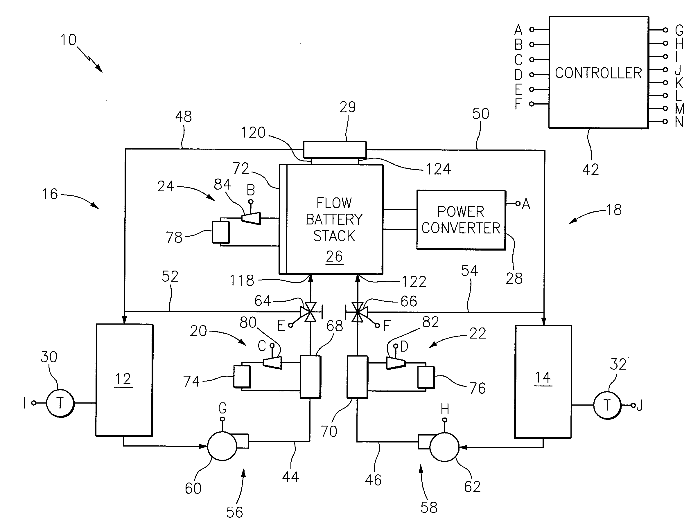
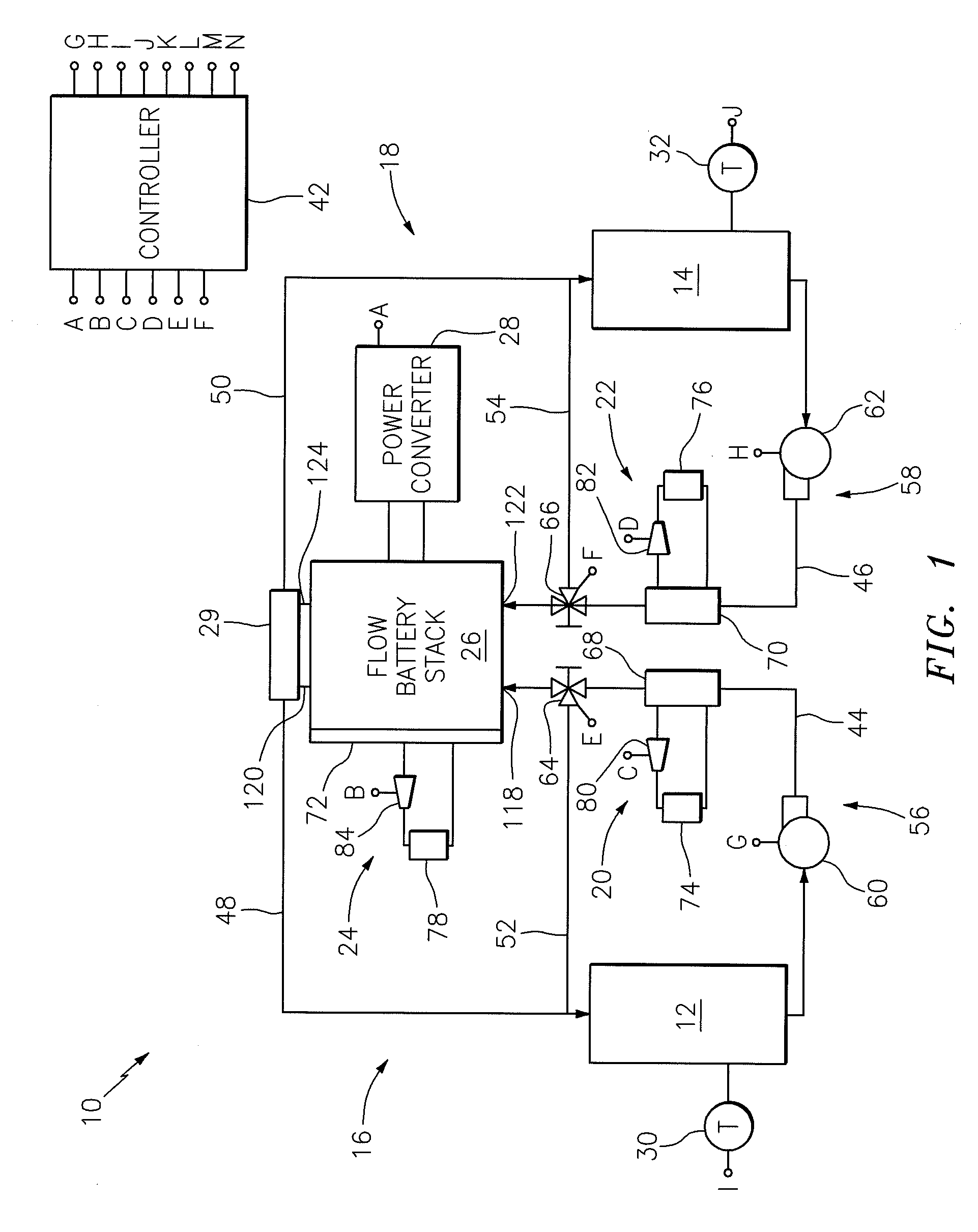
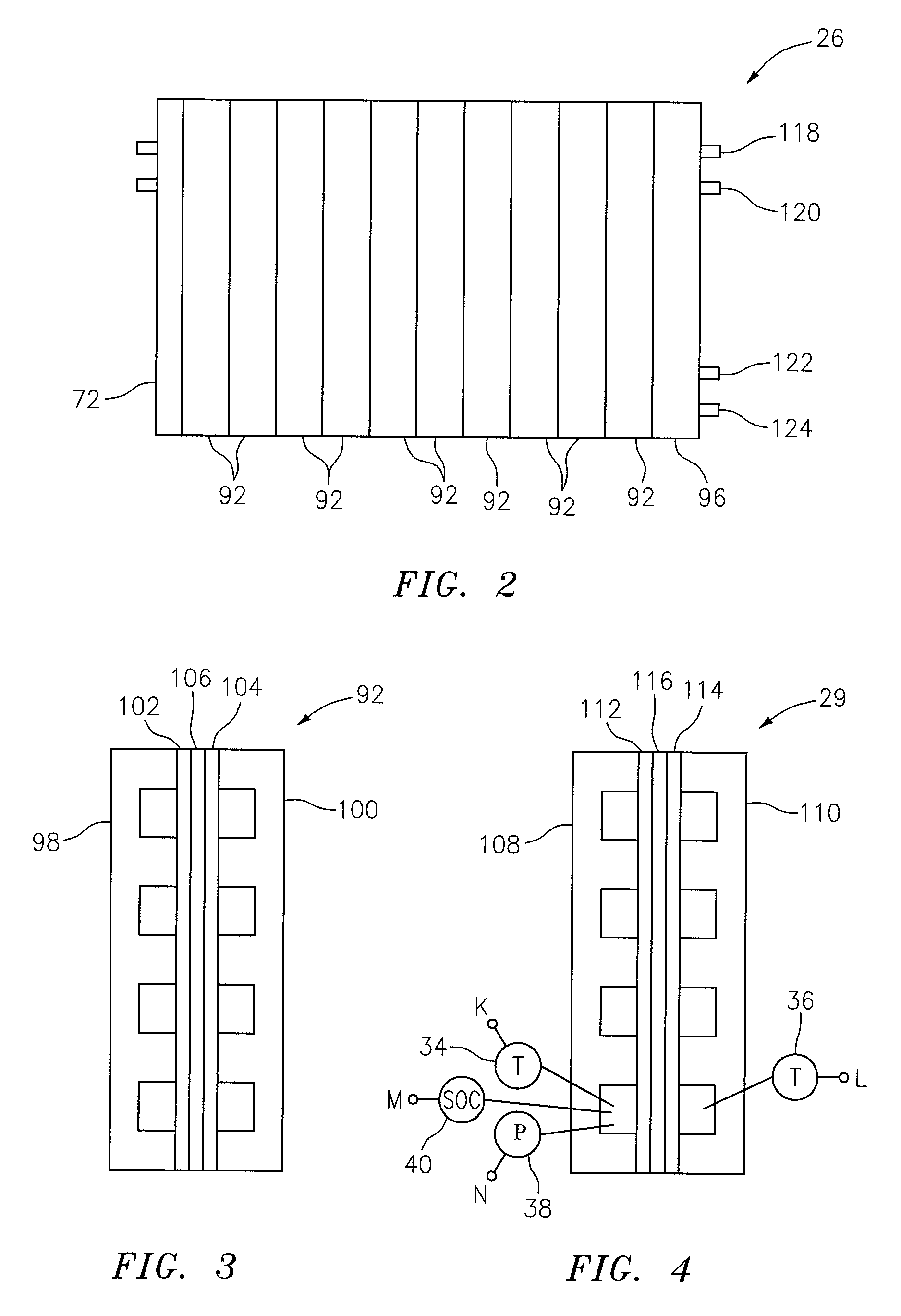
[0013]FIG. 1 illustrates a flow battery system 10. The flow battery system 10 includes a first reservoir 12, a second reservoir 14, a first solution flow circuit 16, a second solution flow circuit 18, a plurality of coolant loops 20, 22 and 24, a flow battery stack 26, a power converter 28, a reference cell 29, a plurality of sensors 30-40 (see FIGS. 1 and 4), and a controller 42.

[0014]The first reservoir 12 contains a first electrolyte solution (e.g., a vanadium catholyte). The second reservoir 14 contains a second electrolyte solution (e.g., a vanadium anolyte).

[0015]The first and second solution flow circuits 16 and 18 may each include a source conduit 44, 46, a return conduit 48, 50, a bypass conduit 52, 54 and a flow regulator 56, 58, respectively. The flow regulator 56, 58 may include a variable speed pump 60, 62, and an electronically actuated three-way valve 64, 66, respectively. The pump 60, 62 and the valve 64, 66 are fluidly connected inline within the source conduit 44, ...


PUM

PropertyMeasurementUnit
temperatureaaaaaaaaaa

Abstract

A flow battery system includes a flow battery stack, a sensor and a coolant loop. The flow battery stack has an electrolyte solution flowing therethrough, and the sensor is in communication with the electrolyte solution. The coolant loop is in heat exchange communication with the electrolyte solution, wherein the heat exchange communication is selective based on an output from the sensor.

Description

CROSS-REFERENCE TO RELATED APPLICATIONS[0001]This application is related to PCT / US09 / 68681, U.S. patent application Ser. No. 13 / 084,156, U.S. patent application Ser. No. 13 / 023,101, and U.S. patent application Ser. No. 13 / 022,285, each of which is incorporated by reference in its entirety.BACKGROUND[0002]1. Technical Field[0003]This disclosure relates generally to a flow battery system and, more particularly, to a system and method for operating a flow battery system at an elevated temperature.[0004]2. Background Information[0005]A typical flow battery system includes a stack of flow battery cells, each cell having an ion-exchange membrane disposed between negative and positive electrodes. During operation, a catholyte solution flows through the positive electrode, and an anolyte solution flows through the negative electrode. The catholyte and anolyte solutions each electrochemically react in a reversible reduction-oxidation (“redox”) reaction. Ionic species are transported across t...

Claims


Application Information

Patent Timeline
Patent Type & Authority Applications(United States)
IPC IPC(8): H01M8/20H01M10/50H01M2/40H01M50/77
CPCH01M8/04029H01M8/04276H01M8/188Y02E60/528H01M8/20H01M2/40H01M10/60Y02E60/50Y02E60/10H01M50/77
Inventor PERRY, MICHAEL L.ZAFFOU, RACHID
Owner RAYTHEON TECH CORP
Why Eureka
Try Eureka