
Lens systems for presbyopia

a technology for presbyopia and lenses, applied in the field of ophthalmic lenses, can solve the problems of loss of stereopsis, bending of natural lenses, and the ability of eyes to accommodate, and the loss of natural lenses

Active Publication Date: 2012-12-27
JOHNSON & JOHNSON VISION CARE INC
View PDF0 Cites 39 Cited by
  • Summary
  • Abstract
  • Description
  • Claims
  • Application Information

AI Technical Summary

Benefits of technology

The invention is a family of lenses that meet certain requirements and have specific shapes. The lenses can have aspheric surfaces and can be used to correct presbyopia. The lenses have different power profiles and can be designed to fit similar to a single monocurve lens. The method for correcting presbyopia involves using multiple lenses with different power profiles. The technical effects of the invention include improved optical performance and improved vision for people with presbyopia.

Problems solved by technology

As a person ages their eyes are less able to accommodate, or bend the natural lens, to focus on objects that are relatively near to the observer.
Similarly, people who have had their natural lens removed and an intraocular lens inserted as a replacement do not generally have the ability to accommodate.
Monovision typically results in a loss of stereopsis.
Satisfactory corrections can be obtained with this method but it typically results in a reduction of image contrast and resolution compared to monovision.

Method used


Image

  • Lens systems for presbyopia
  • Lens systems for presbyopia
  • Lens systems for presbyopia

Examples


example 1

[0067]A system of lenses is made up across a range of distance corrective powers and three add powers. Each lens has radial zones of varying power. The central zone has power that is more plus or “near” so this lens has a “center near” design. The lenses are designated as “A”, “B”, and “C” and individually provide progressively better near vision performance. The power profiles for the exemplary −3.0 D lens of this system of lenses are shown in FIG. 7.

[0068]The following table shows by add need (+0.75 to +2.50 D) the lens pairs that meet the criteria for the family of lenses of the invention. The AA pair (an A lens in each of the two eyes) meets the above requirements for 0.75, 1.0, and 1.25 D add requirement. The AB pair does not meet the requirement for any add powers. For 1.50, 1.75, and 2.00 D add requirement either the BB or the BC pair meets the requirements. For high adds the BC pair is required. There is a pair of lenses that meets the above constraints for each add requirem...

example 2

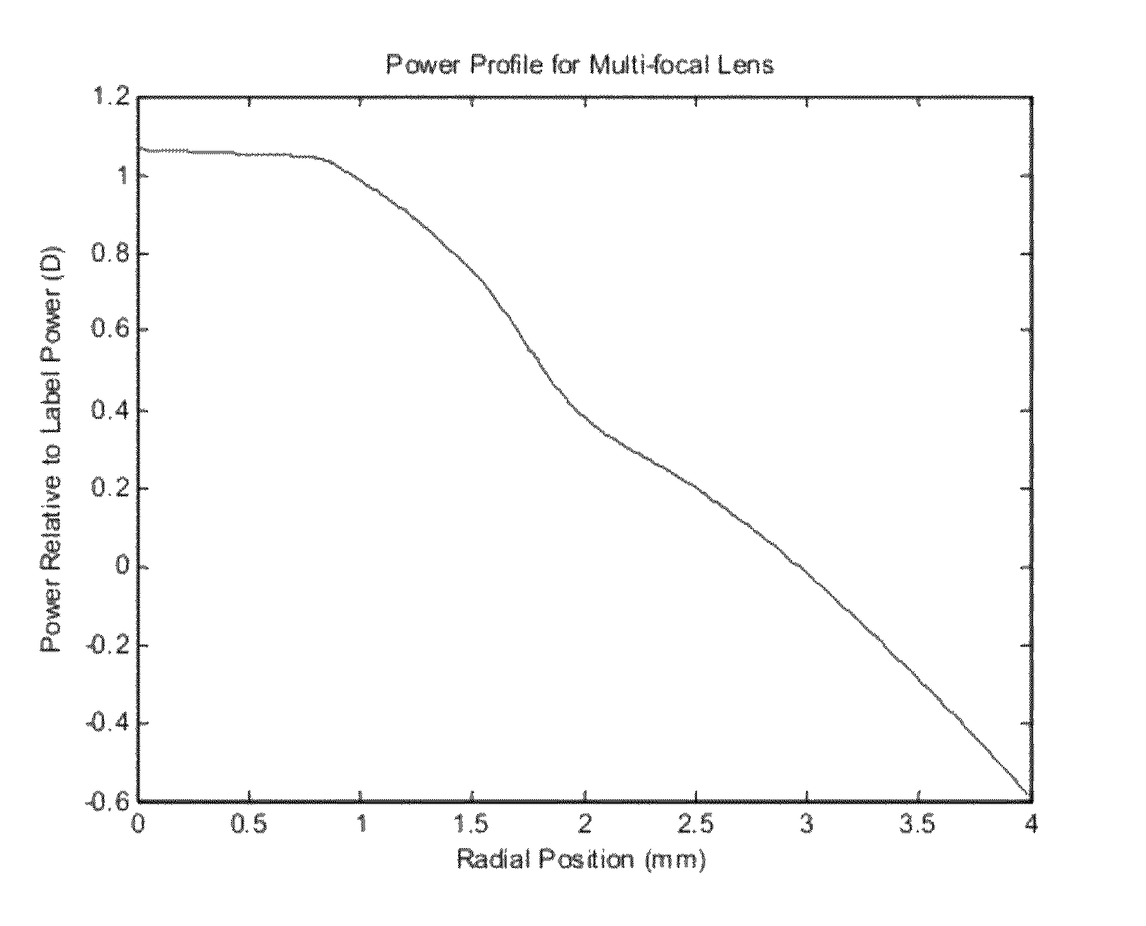
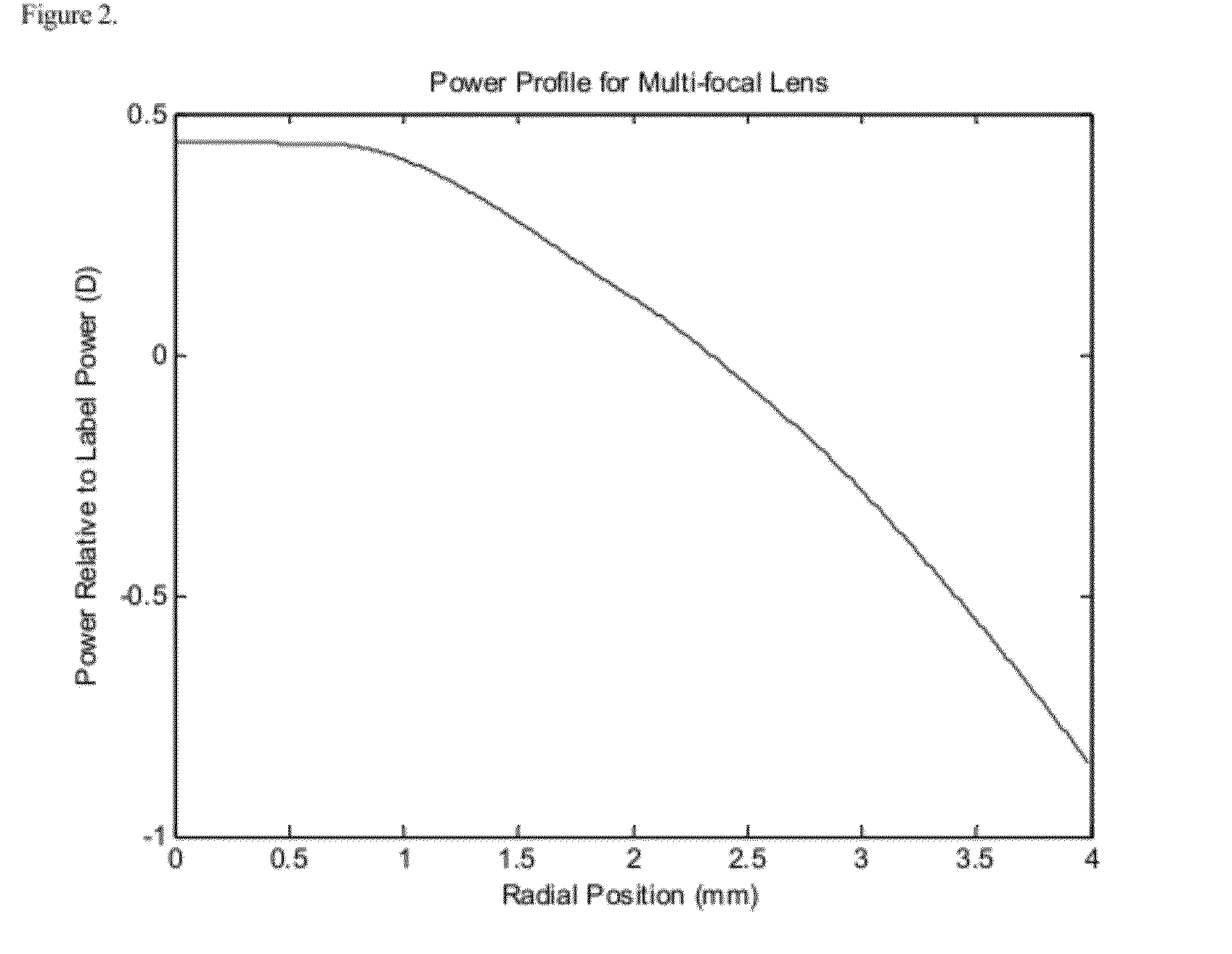
[0069]A system of lenses is made up across a range of distance corrective powers and three add powers. The central zone has power that is more plus or “near” and the optic zone is a continuous asphere, so lens is a “center near continuous asphere” design. The lenses are designated as “A”, “B”, and “C” and provide progressively better near vision performance. The power profiles for the exemplary −3.00 D lenes are shown in FIGS. 2, 3 and 4.

[0070]The following table shows the pairs by add that meet the criteria for the family of lenses of the invention. There is at least one pair of lenses that meets the requirement for all add powers.

Continuous Asphere0.7511.251.51.7522.252.5AA+++ABBB+++BC++

example 3

[0071]A system of lenses is made up across a range of distance corrective powers and three add powers. In this case the central zone has more minus power than the adjacent zone so the lens has a “center distance” ring design. The lenses are designated as “A”, “B”, and “C” and provide progressively better near vision performance The power profiles for the exemplary −3.00 D lenses are shown in FIG. 8. The following table shows the pairs by add that meet the above constraints. There is at least one pair of lenses that meets the requirement for all add powers.

Center Distance0.7511.251.51.7522.252.5AA+++AB+BB+++BC+++


PUM


Abstract

A family of ophthalmic lenses for correcting presbyopia meets constraints for distance vision, near vision, and disparity and may be designed according to a process that incorporates a merit function accounting for binocular visual performance.

Description

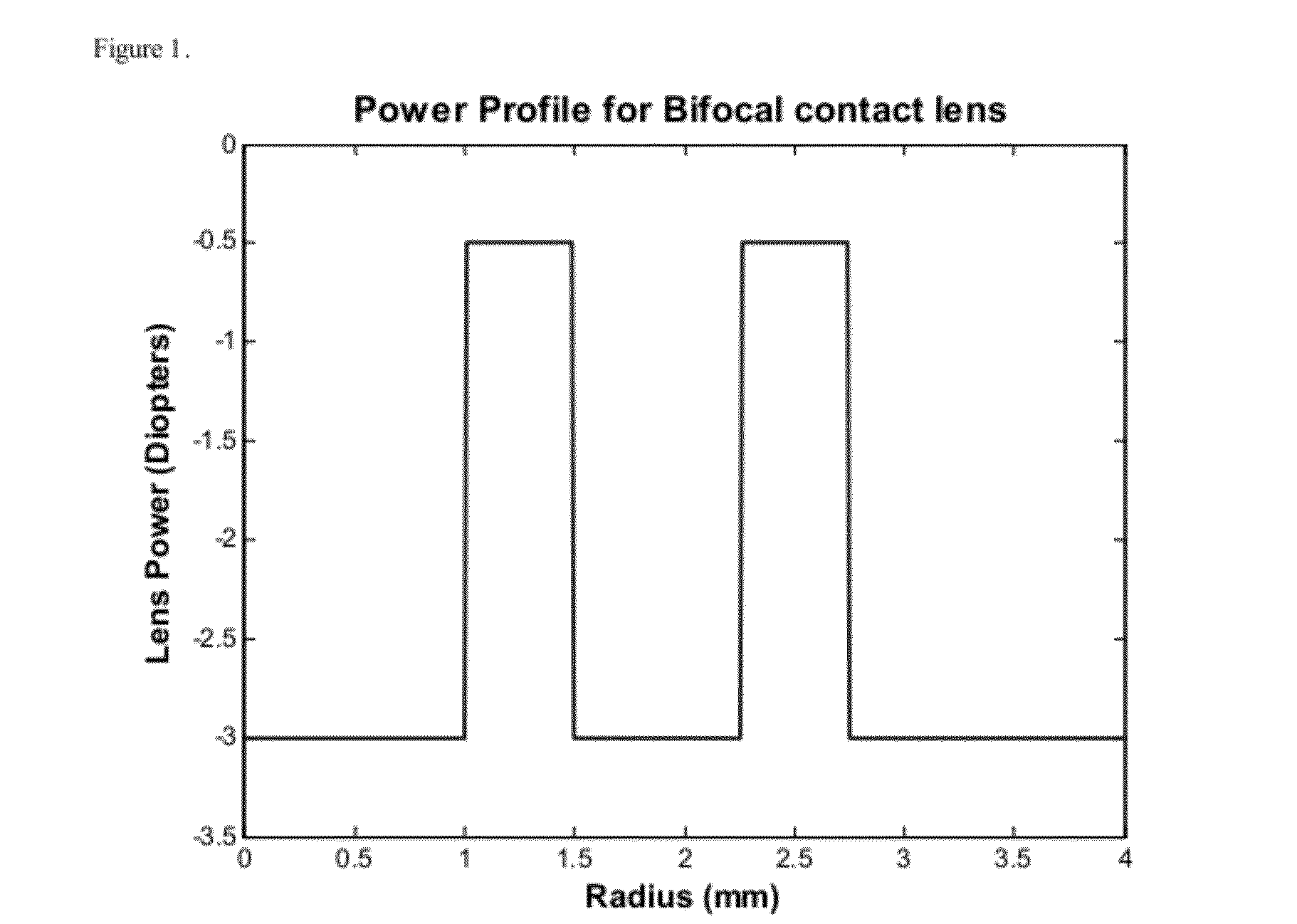
BACKGROUND[0001]The invention relates to ophthalmic lenses useful for the correction of presbyopia.[0002]As a person ages their eyes are less able to accommodate, or bend the natural lens, to focus on objects that are relatively near to the observer. This condition is known as presbyopia. Similarly, people who have had their natural lens removed and an intraocular lens inserted as a replacement do not generally have the ability to accommodate.[0003]One method to correct for the eye's failure to accommodate is known as monovision in which a single vision lens for correction of distance vision is used in the dominant eye and a single vision lens for correction of near vision is used in the non-dominant eye. Monovision typically results in a loss of stereopsis. Another method for treating presbyopia is the use of bifocal or multifocal contact lenses in both of the individual's eyes. Satisfactory corrections can be obtained with this method but it typically results in a reduction of ima...

Claims


Application Information

Patent Timeline
Patent Type & Authority Applications(United States)
IPC IPC(8): G02C7/02
CPCG02C7/044G02C7/042G02C2202/22
Inventor WOOLEY, C. BENJAMINKARKKAINEN, THOMAS R.CLARK, RONALD J.
Owner JOHNSON & JOHNSON VISION CARE INC
Learn More