Optical deflector including piezoelectric sensor on support body

Active Publication Date: 2012-12-27
STANLEY ELECTRIC CO LTD
View PDF2 Cites 13 Cited by
  • Summary
  • Abstract
  • Description
  • Claims
  • Application Information

AI Technical Summary

Benefits of technology

[0010]According to the presently disclosed subject matter, in an optical deflector including a mirror, a support body, and a piezoelectric actuator connected to the support body for rocking the mirror with respect to an axis of the mirror, at least one piezoelectric sensor is provided on the support body to sense a rocking vibration of the mirror caused by the piezoelectric actuator. Since the piezoelectric actuator includes no sense elements, the rocking force of the piezoelectric actuator is strengthened.
[0011]Also, the p

Problems solved by technology

In the above-described prior art two-dimensional optical deflector, however, since the sense elements are provided in the piezoelectric actuators, the provision of the drive elements in the piezoelectric actuators is decreased so that the rocking forces of the piezoelectric actuators are

Method used


Image

  • Optical deflector including piezoelectric sensor on support body
  • Optical deflector including piezoelectric sensor on support body
  • Optical deflector including piezoelectric sensor on support body

Examples


first embodiment

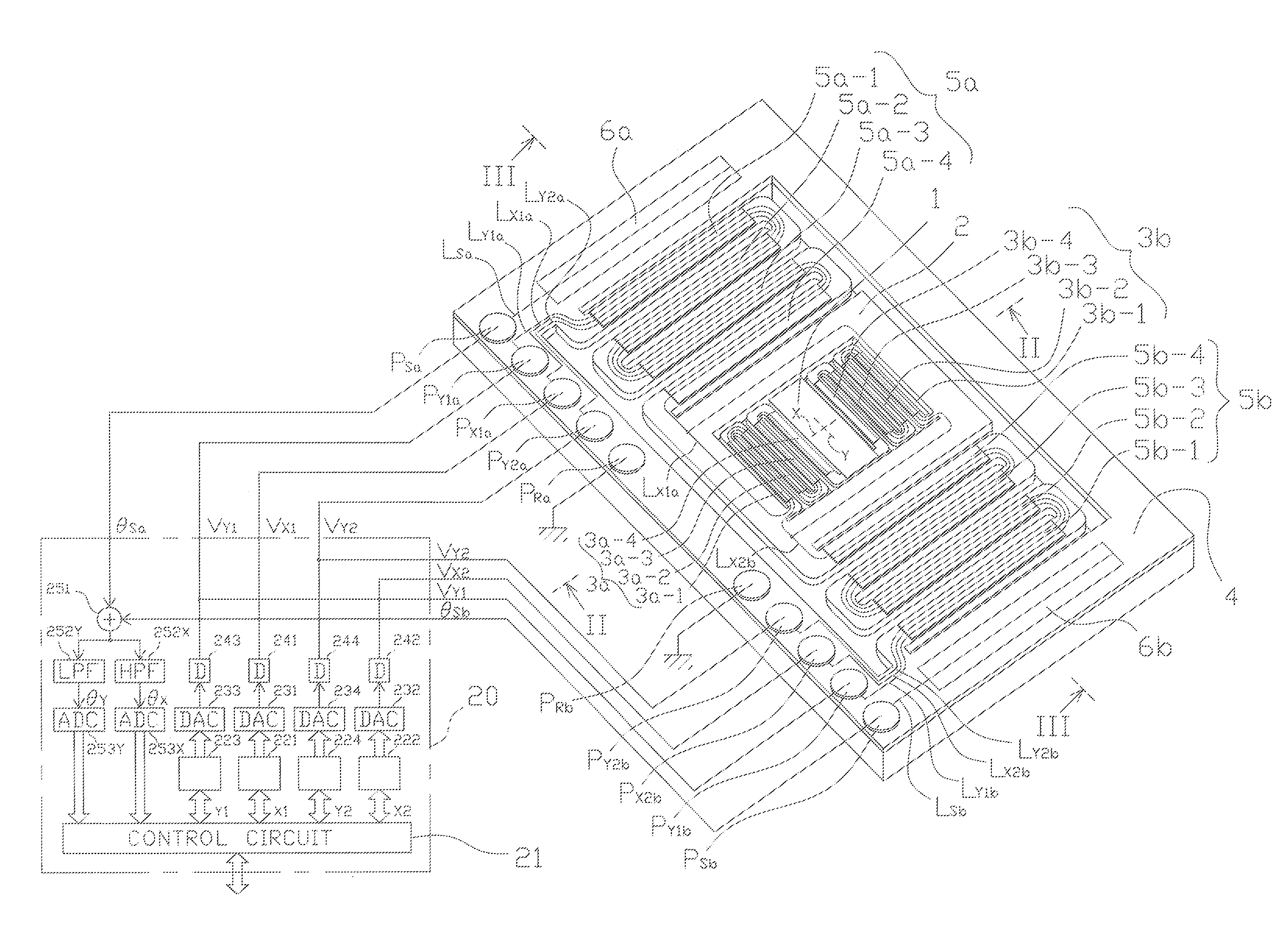
[0026]In FIG. 1, which illustrates the optical deflector according to the presently disclosed subject matter, reference numeral 10 designates a two-dimensional optical deflector, and 20 designates a driver for driving the two-dimensional optical deflector 10.

[0027]The optical deflector 10 is constructed by a rectangular mirror 1 for reflecting an incident light, a movable frame 2 surrounding the mirror 1 for supporting the mirror 1, a pair of meander-type inner piezoelectric actuators 3a and 3b fixed between the movable frame 2 and the mirror 1 and serving as cantilevers for rocking the mirror 1 with respect to an X-axis of the mirror 1, a support body 4 surrounding the movable frame 2, a pair of meander-type outer piezoelectric actuators 5a and 5b fixed between the support body 4 and the movable frame 2 and serving as cantilevers for rocking the mirror 1 through the movable frame 2 with respect to a Y-axis of the mirror 1 perpendicular to the X-axis, and piezoelectric sensors 6a an...

second embodiment

[0080]FIG. 7 illustrates the optical deflector according to the presently disclosed subject matter, and FIG. 8 is a cross-sectional view taken along the VIII-VIII line in FIG. 7. That is, as illustrated in FIGS. 7 and 8, recess portions 4a and 4b are provided in the support body 4 under the piezoelectric sensors 6a and 6b, respectively. In more detail, the thickness of the support body 4 under the piezoelectric sensors 6a and 6b is the same as that of the sum of the monocrystalline silicon active layer 203 and the silicon dioxide layer 204.

[0081]In order to maintain the rigidity of the support body 4, the support body 4 is preferably as thick as possible; however, when the support body 4 is too thick, the rocking vibration by the inner piezoelectric actuators 3a and 3b and the rocking vibration by the outer piezoelectric actuators 5a and 5b hardly propagate to the piezoelectric sensors 6a and 6b. Therefore, the provision of the recess portions 4a and 4b enhances the propagation of t...


PUM


Abstract

In an optical deflector including a mirror, a support body, and a piezoelectric actuator connected to the support body for rocking the mirror with respect to an axis of the mirror, at least one piezoelectric sensor is provided on the support body to sense a rocking vibration of the mirror caused by the piezoelectric actuator.

Description

[0001]This application claims the priority benefit under 35 U.S.C. §119 to Japanese Patent Application No. JP2011-138622 filed on Jun. 22, 2011, which disclosure is hereby incorporated in its entirety by reference.BACKGROUND[0002]1. Field[0003]The presently disclosed subject matter relates to an optical deflector including sense elements (piezoelectric sensors).[0004]2. Description of the Related Art[0005]A prior art two-dimensional optical deflector is constructed by a mirror, a movable frame surrounding the mirror for supporting the mirror, a pair of meander-type inner piezoelectric actuators fixed between the movable frame and the mirror and serving as cantilevers for rocking the mirror with respect to an X-axis of the mirror, a support body surrounding the movable frame, and a pair of meander-type outer piezoelectric actuators fixed between the support body and the movable frame and serving as cantilevers for rocking the mirror through the movable frame with respect to a Y-axis ...

Claims


Application Information

Patent Timeline
IPC IPC(8): G02B26/10
CPCG02B26/101G02B26/0858
Inventor KOYAMA, TAKAAKI
Owner STANLEY ELECTRIC CO LTD
Why Eureka
Try Eureka