Measurement control method
- Summary
- Abstract
- Description
- Claims
- Application Information
AI Technical Summary
Benefits of technology
Problems solved by technology
Method used
Image
Examples
first embodiment
[0038]An embodiment in a case in which the present invention is applied to a Long Term Evolution (LTE) system will be described below.
[0039](System Configuration)
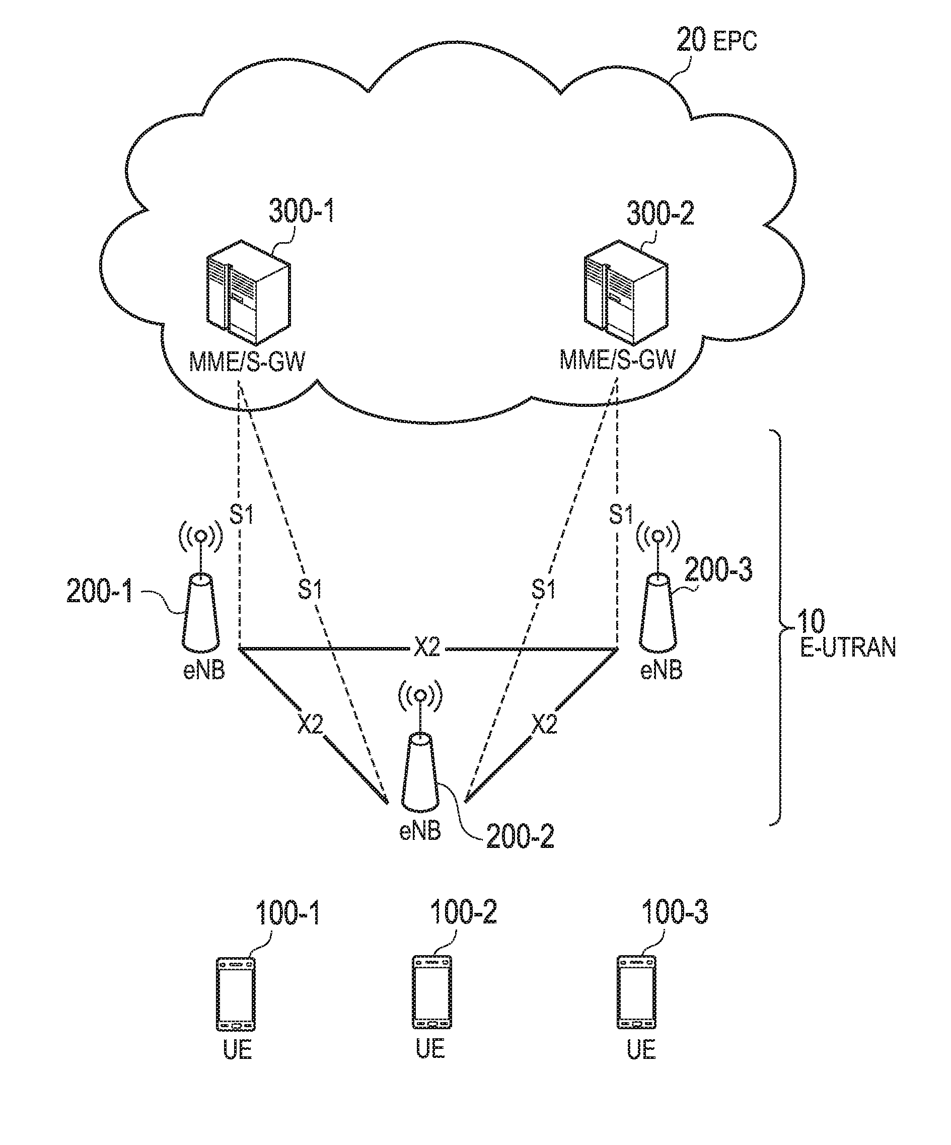
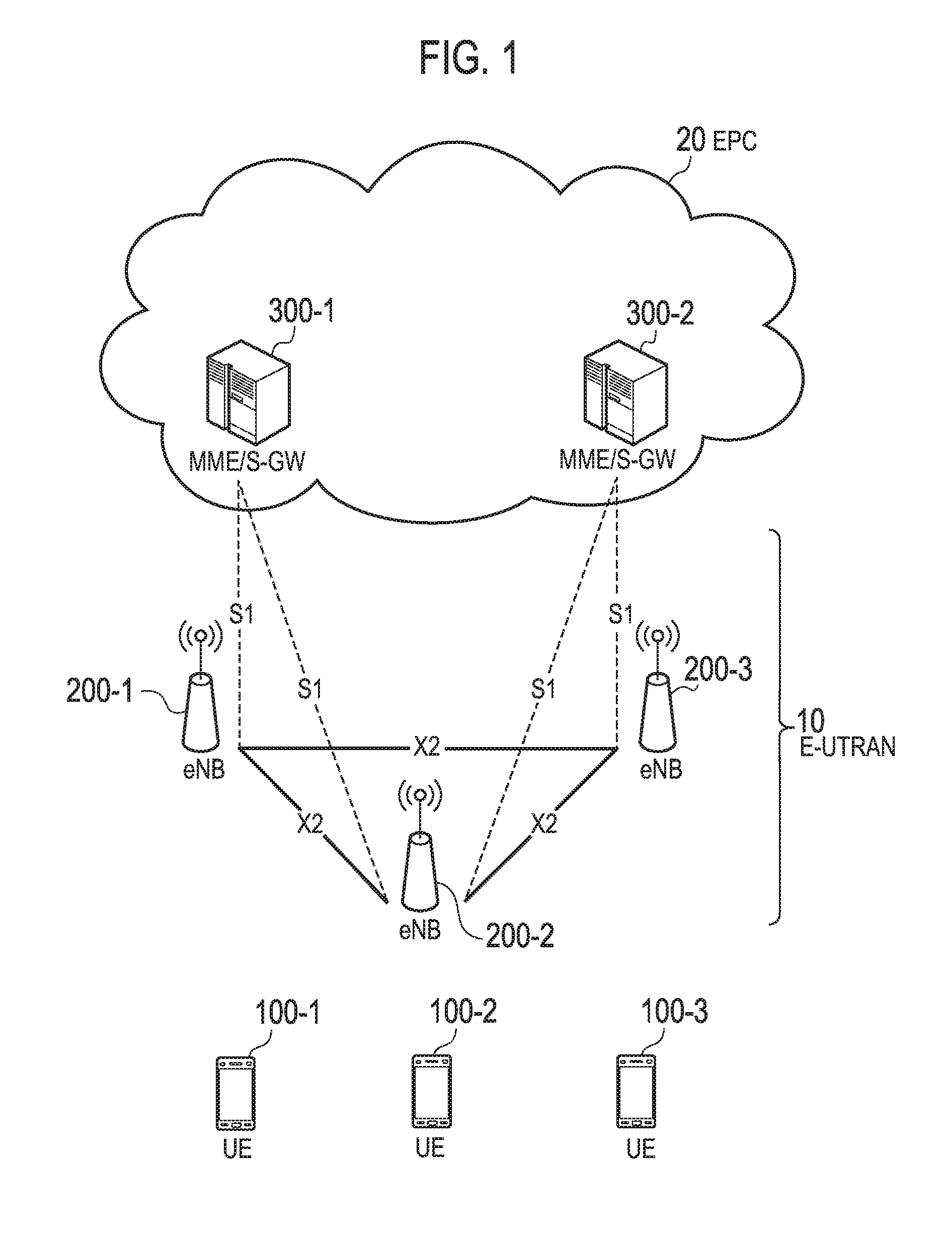
[0040]FIG. 1 is a configuration diagram of the LTE system according to the first embodiment. As illustrated in FIG. 1, the LTE system according to the first embodiment includes UEs (User Equipments) 100, E-UTRAN (Evolved Universal Terrestrial Radio Access Network) 10, and EPC (Evolved Packet Core) 20.
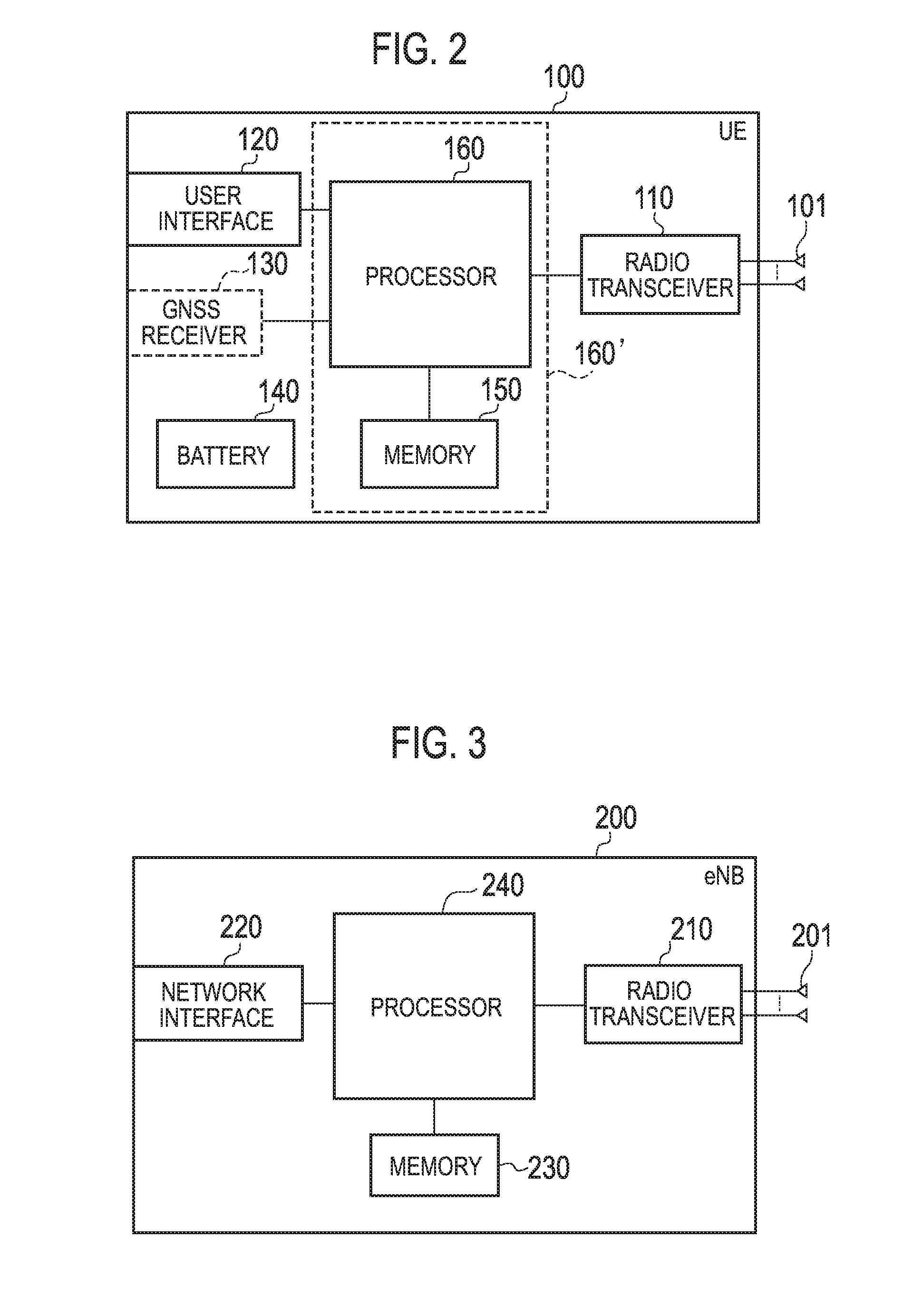
[0041]The UE 100 corresponds to the user terminal. The UE 100 is a mobile radio communication apparatus and performs radio communication with a cell (a serving cell). The configuration of the UE 100 will be described later.
[0042]The E-UTRAN 10 corresponds to a radio access network. The E-UTRAN 10 includes eNBs 200 (evolved Node-Bs). The eNB 200 corresponds to a base station. The eNBs 200 are connected mutually via an X2 interface. The configuration of the eNB 200 will be described later.
[0043]The eNB 200 manages one or more cel...
second embodiment
Modified Example of Second Embodiment
[0123]In the above-described second embodiment, an uplink latency is measured using a BSR. Here, the UE 100 manages data amounts accumulated in an uplink buffer for every priority (every QCI). In the current specification, if a new uplink packet with higher priority than that of existing data in an uplink buffer of the UE 100 is generated, a BSR is triggered. In contrast, if a new uplink packet with lower priority than that of the existing data is generated, a BSR is not triggered. It is therefore difficult to apply the measurement control method according to the second embodiment to a case of measuring a latency of an uplink packet with low priority.
[0124]FIG. 8 is a sequence diagram illustrating an operation performed in a case in which an uplink packet with low priority is generated in the measurement control method according to the second embodiment. The description will now be given mainly based on a difference from the above-described secon...
third embodiment
[0149]The third embodiment will be described below mainly based on a difference from the first and second embodiments. A system configuration according to the third embodiment is similar to that according to the first embodiment.
[0150]The third embodiment shares a common point with the second embodiment in that an uplink latency is measured. Nevertheless, the third embodiment differs from the second embodiment in that a measuring subject is the eNB 200 in the second embodiment, whereas a measuring subject is the UE100 in the third embodiment.
[0151]A method by which the UE 100 in the idle state performs measurement and collection to store measurement information, and transmits the measurement information to a network later is defined in the current specification, and referred to as Logged MDT. In the third embodiment, the UE 100 in the connected state performs measurement and collection, and transmits measurement information to a network. Such a method is sometimes referred to as Log...
PUM
 Abstract
Description
Claims
Application Information
 - R&D
- Intellectual Property
- Life Sciences
- Materials
- Tech Scout
- Unparalleled Data Quality
- Higher Quality Content
- 60% Fewer Hallucinations
Browse by: Latest US Patents, China's latest patents, Technical Efficacy Thesaurus, Application Domain, Technology Topic, Popular Technical Reports.
© 2025 PatSnap. All rights reserved.Legal|Privacy policy|Modern Slavery Act Transparency Statement|Sitemap|About US| Contact US: help@patsnap.com


