Multiplane medical imaging system

a medical imaging and multi-plane technology, applied in the field of medical imaging systems, can solve the problems of affecting the placement of patients on the examination table, the system cannot be moved away from the examination table when not in use, and the need for radiography, so as to increase the freedom of x-ray machines and increase their ability to mov

Active Publication Date: 2012-12-27
GENERAL ELECTRIC CO
View PDF4 Cites 37 Cited by
  • Summary
  • Abstract
  • Description
  • Claims
  • Application Information

AI Technical Summary

Problems solved by technology

This type of system, however, has a major drawback relating to the fact that the radiography need is only necessary during a limited time of the procedure.
The systems can therefore not be moved away from the examination table when they are not in use.
In particular, the transfer and the placement of the patient on the examination table are hampered by the presence of this cumbersome system.
This type of system is not suitable for angiographic examinations because the power delivered by the X-ray tube is not sufficient to obtain adequate image quality and, in particular, adequate contrast.
Moreover, this type of mobile X-ray system does not allow complex angulations because the diameter of the arm supporting the tube and the detector is not big enough.
Similarly, these mobile X-ray systems do not achieve sufficient rotation speeds to allow good quality, three-dimensional image reconstructions.
Finally, even though the weight of such a system is half as much as that of an X-ray machine designed for angiography, it remains very difficult to move because of its relatively large dimensions and weight, which can be up to about 300 kg (about 660 lbs).
In this type of medical imaging system, the X-ray machines are relatively bulky so that, during the radiological examination, access to the patient on an examination table is considerably limited.
This access limitation is due to the location of the first X-ray machine.
Being fixed to the floor in the vicinity of the frontal zone of an examination or operating table on which the patient is located, considerably limits access to the patient.
Moreover, the radiographic requirements for certain examinations or interventions are necessary only for a limited period of the procedure.
Here again, fixing the robot to the floor is likely to limit the ability to move the X-ray machine.

Method used


Image

  • Multiplane medical imaging system
  • Multiplane medical imaging system
  • Multiplane medical imaging system

Examples


Embodiment Construction

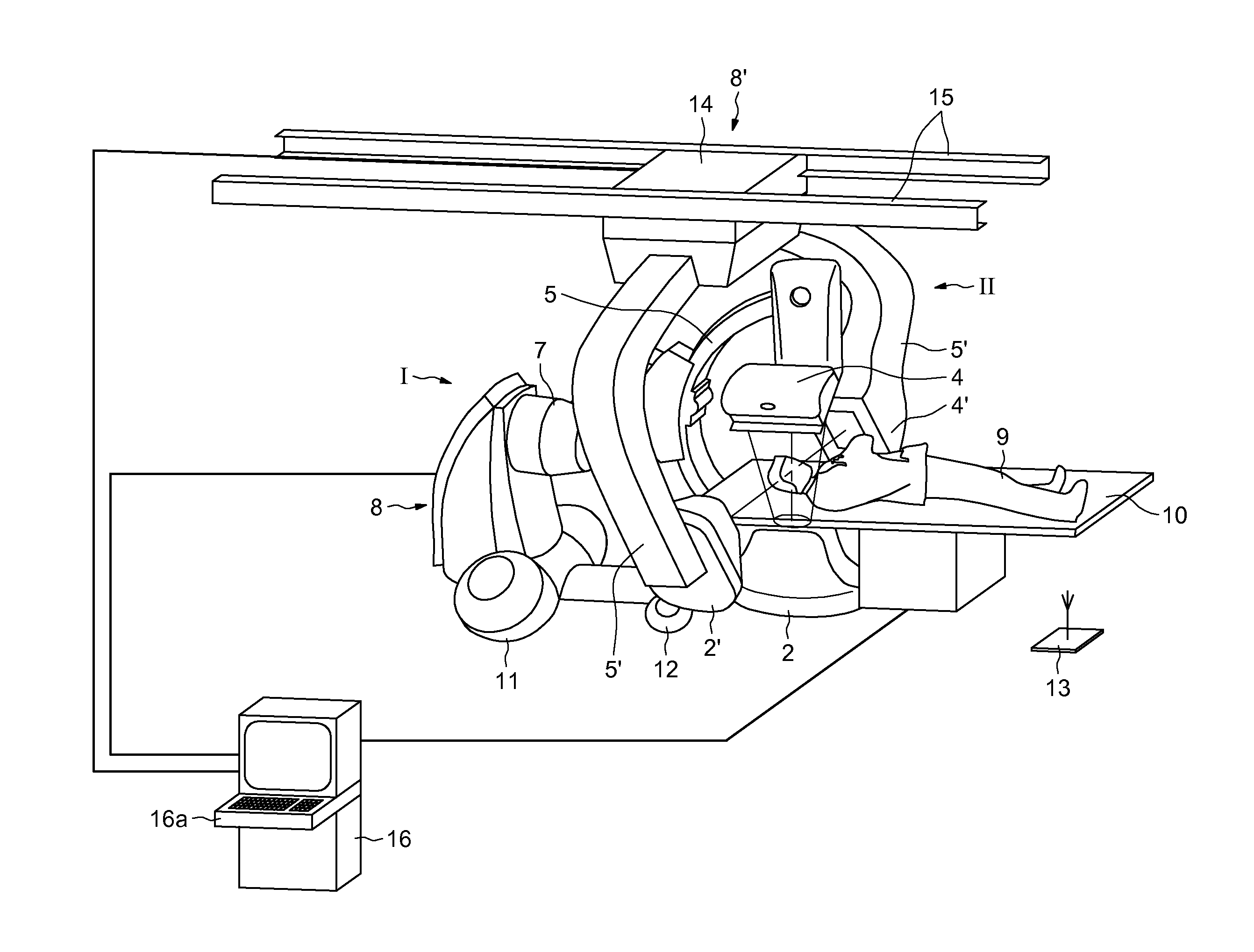
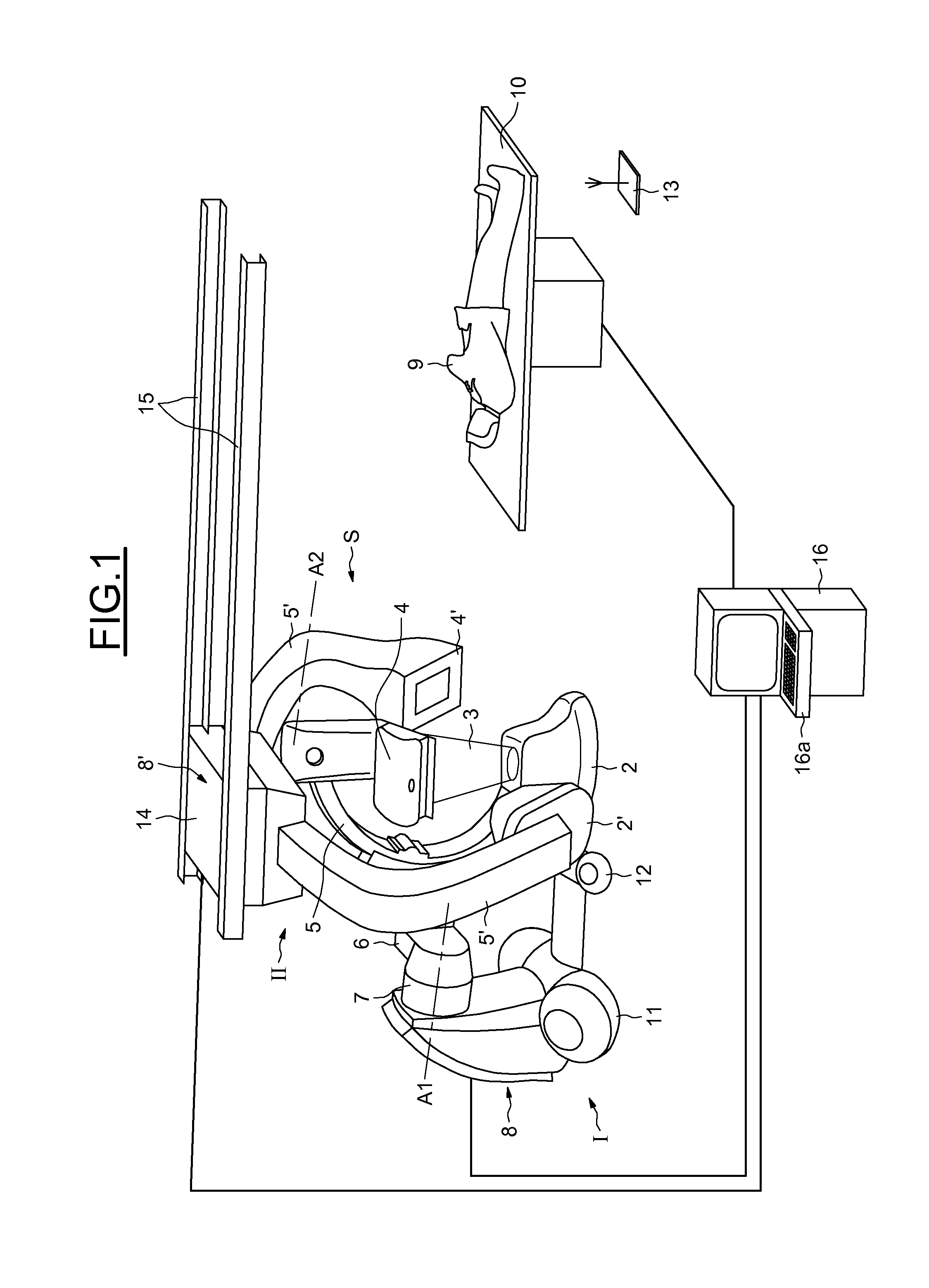
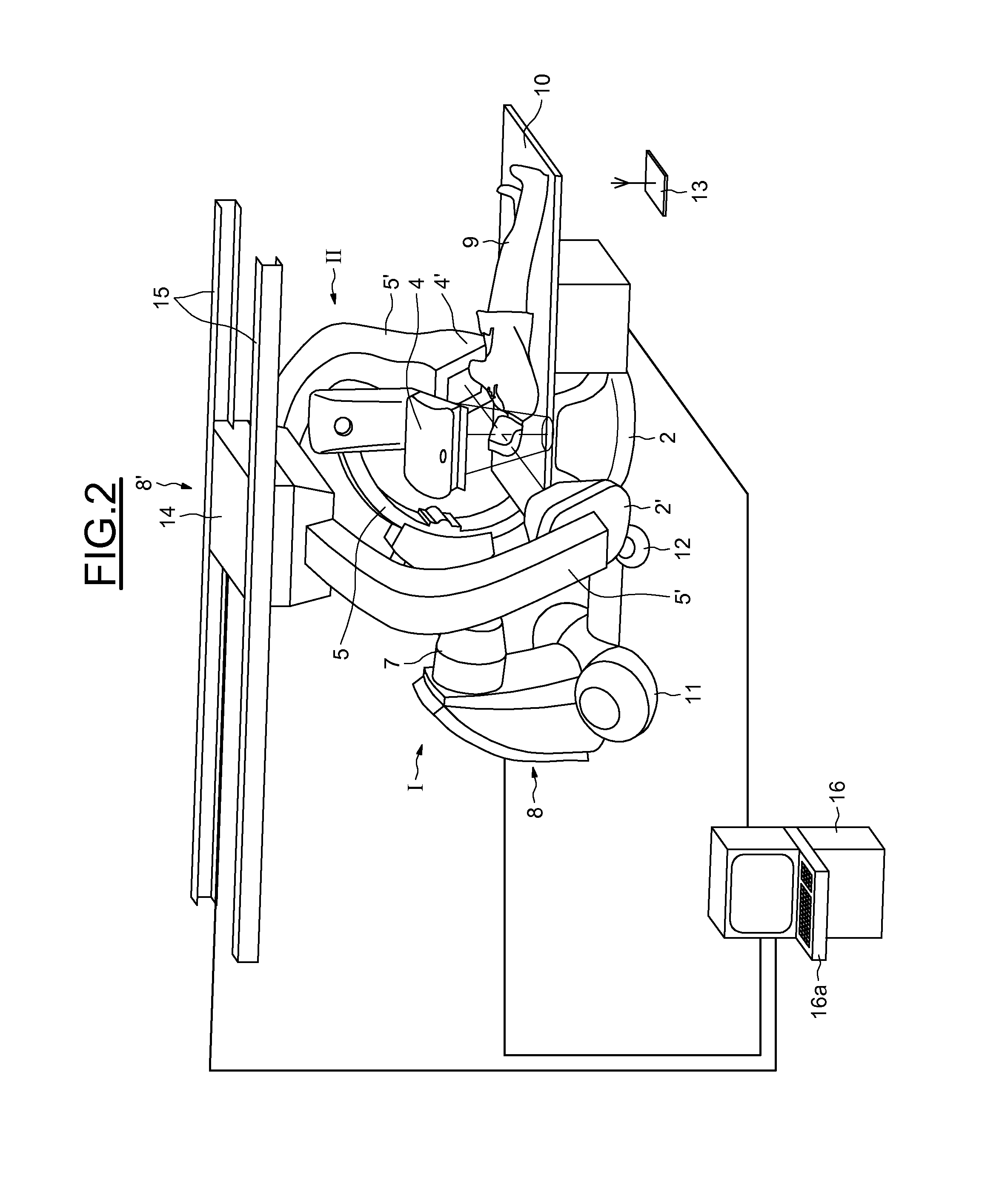
[0026]FIG. 1 illustrates a vascular biplane medical imaging system. The imaging system may be used for an angiographic examination and is especially designed to provide views on two different planes of a vessel in order to view them in these two planes, which in this instance, are perpendicular.

[0027]The imaging system S is equipped with two X-ray machines I, II, each ensuring a view in one plane.

[0028]These two machines I, II, are each mounted on a mobile robotic device and are each capable of moving according to the examination phases. The first X-ray machine I can be moved on the floor, while the second machine II can be moved on the ceiling of an examination or operating room.

[0029]The first machine I comprises an X-ray tube 2, capable of emitting a beam 3 of X-rays in an emission direction, and an X-ray detector 4 placed at the two mutually opposite ends of an arm 5, in this instance in the form of an arch, so that the X-rays emitted by the tube 2 are incident to the detector 4...


PUM


Abstract

A multiplane medical imaging system is provided. The multiplane medical imaging system comprises a first X-ray machine and a second X-ray machine, each X-ray machine comprising an X-ray tube and an X-ray detector, wherein the first and second X-ray machines each comprise respective mobile automatic devices on which the respective X-ray tubes and the respective X-ray detectors are mounted in order to control the movement of the first and second X-ray machines.

Description

BACKGROUND OF THE INVENTION[0001]1. Field of the Invention[0002]Embodiments of the invention relate to medical imaging systems and, more particularly, to multiplane medical imaging systems capable of producing radiographic images in several planes and allowing the examination of an area of interest in several planes.[0003]2. Description of Related Art[0004]Imaging systems usually comprise an X-ray machine comprising an X-ray tube and an X-ray detector placed opposite the X-ray tube in the direction of emission of X-rays. The tube and the detector are usually placed on two mutually opposite ends of an arm.[0005]Such systems are used for angiographic examinations for diagnostic or interventional purposes. During these examinations, it is necessary to produce radiographs by X-rays of an area of interest in the body of a patient. For this purpose, after the patient has been laid out on an examination table, the X-ray tube and the detector are brought to face the area to be radiographed....

Claims


Application Information

Patent Timeline
Patent Type & Authority Applications(United States)
IPC IPC(8): A61B6/02
CPCA61B6/4014A61B6/4476A61B6/504A61B6/4464A61B6/547A61B6/4458A61B6/5223
Inventor BOUVIER, BERNARD
Owner GENERAL ELECTRIC CO
Why Eureka
Try Eureka