
Microphone unit, and speech input device provided with same

a microphone and speech input technology, applied in the direction of electrical transducers, electrical transducers, transducer types, etc., can solve the problems of reducing thickness, reducing thickness, and reducing thickness, so as to minimize background noise and minimize the null points of the directionality of the microphone unit. , the effect of minimizing functionality and snr

Active Publication Date: 2012-12-27
FUNAI ELECTRIC CO LTD
View PDF4 Cites 78 Cited by
  • Summary
  • Abstract
  • Description
  • Claims
  • Application Information

AI Technical Summary

Benefits of technology

[0028]According to the present invention, sound that is inputted to the first diaphragm and the second diaphragm from a third opening, which serves as a common sound hole, is transmitted at identical pressure to both of the diaphragms, and therefore, by performing an arithmetic operation on the electrical signal outputted from the first diaphragm and the electrical signal outputted from the second diaphragm, the signal transmitted to the top surface of the first diaphragm can be completely canceled out, and the signal transmitted to the bottom surface of the first diaphragm can be isolated and extracted.
[0059](14) The speech input device according to the present invention may have the microphone unit described in aspect (1) to (13) installed therein. According to aspect (14), there can be realized a speech input device of a thin profile, that minimizes the null points of the directionality of the microphone unit of the speech input device, and that has both background noise minimizing functionality and SNR.

Problems solved by technology

However, in environments in which speech input devices are used, sounds other than intended speech, such as background noise, may be present as well.
A resultant problem is that, due to the additional thickness, reducing thickness becomes difficult.
However, problems are presented in that, because the thickness of the resulting microphone is approximately doubled, reducing thickness becomes difficult.

Method used


Image

  • Microphone unit, and speech input device provided with same
  • Microphone unit, and speech input device provided with same
  • Microphone unit, and speech input device provided with same

Examples


first modification example

[0122]In order to maximize the distance decay rate of a bidirectional microphone, specifically, to maximize the effect of minimizing distant noise, it is necessary to design the figure “8” directionality pattern to have good symmetry.

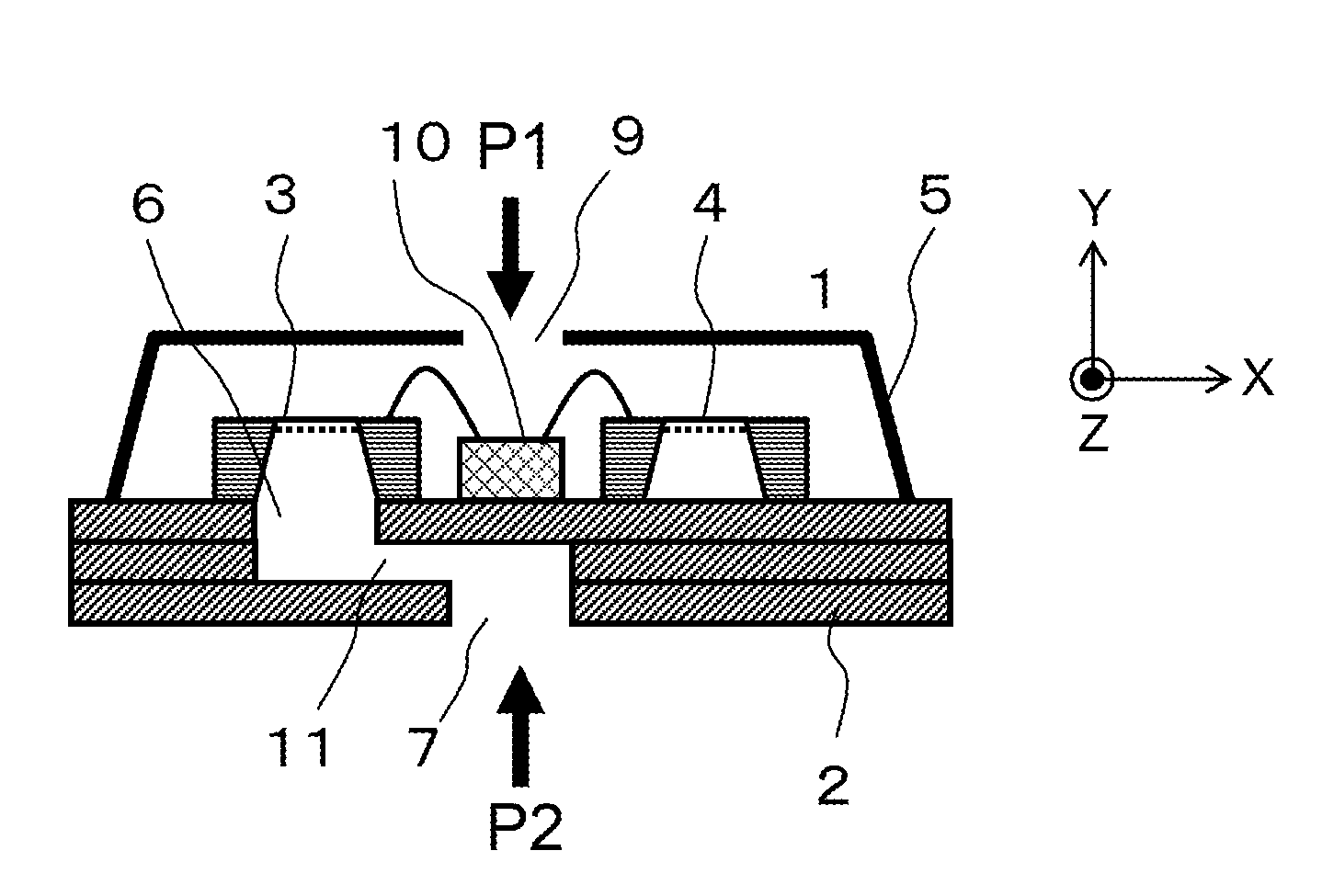
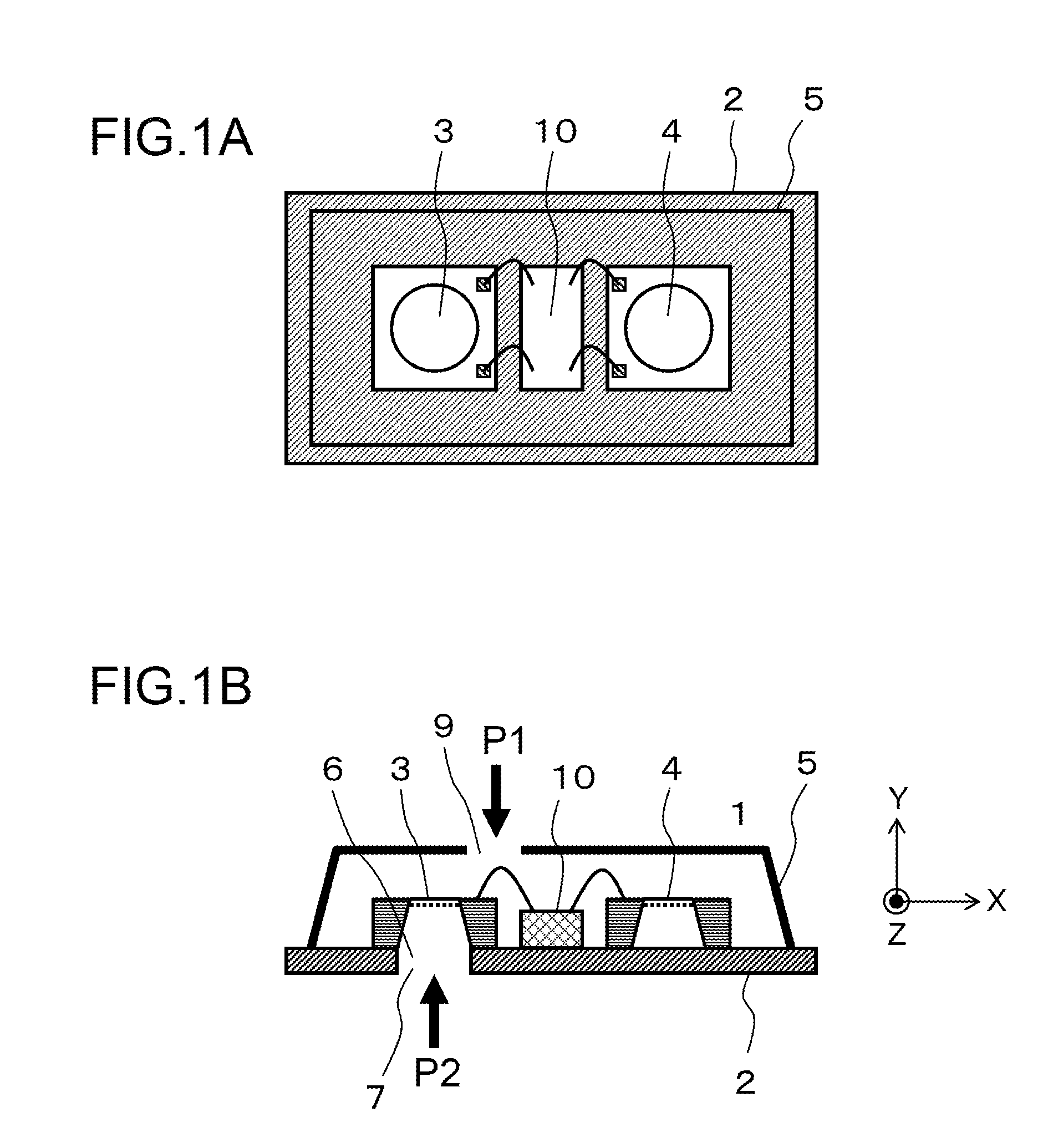
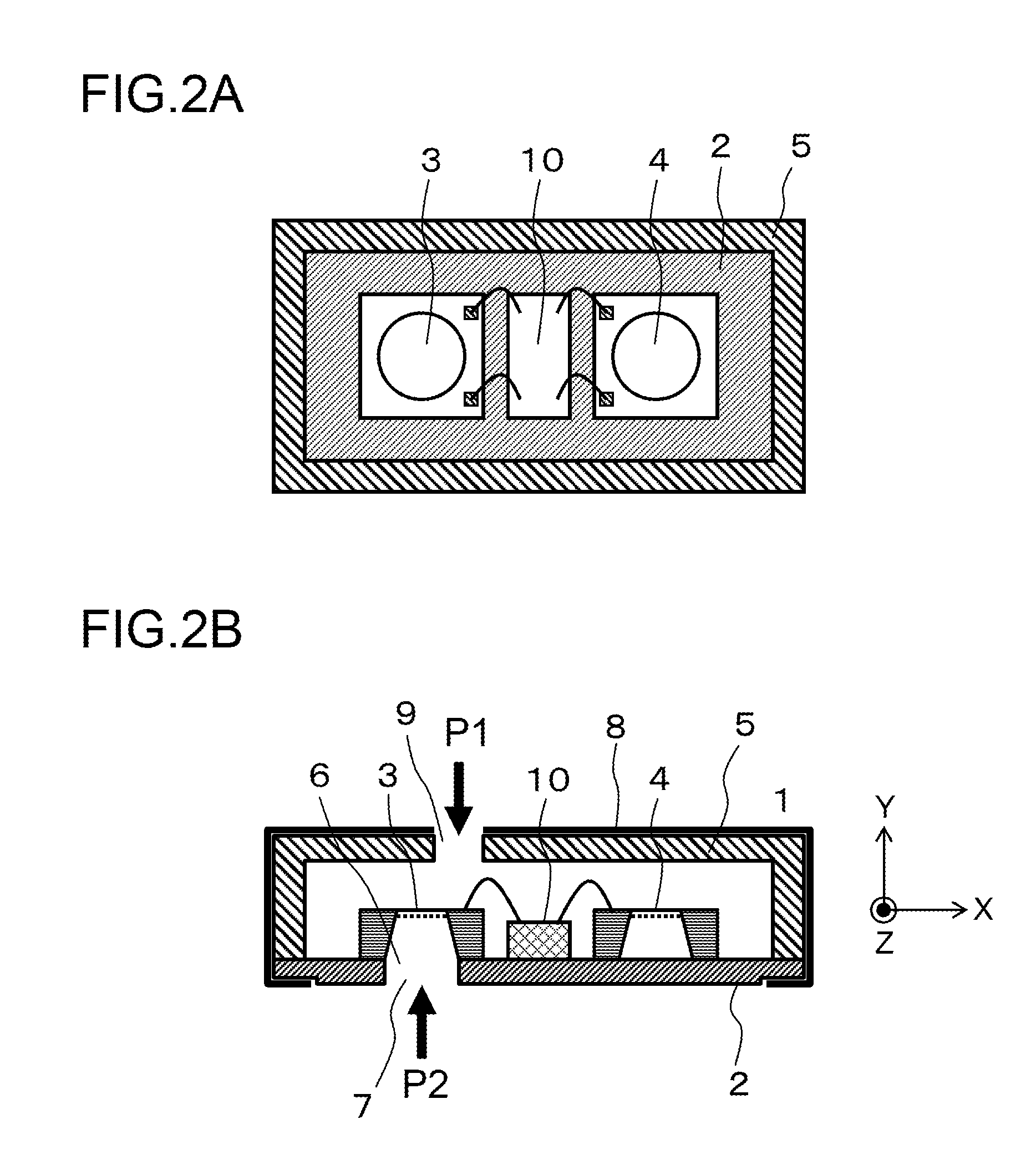
[0123]To this end, it is preferable to adopt a configuration whereby the propagation distance d1 of sound from the second opening 7 of the microphone unit 1 to the bottom surface of the first diaphragm, and the propagation distance d2 of sound from the from the third opening 9 to the top surface of the first diaphragm 3, are equal.

[0124]In FIG. 1A and FIG. 1B, or FIG. 2A and FIG. 2B, the second opening 7 is directly below the first diaphragm 3, and therefore in order to minimize the difference between the propagation distance d1 and the propagation distance d2, there was no other option but to bring the third opening 9 close to right above the first diaphragm 3.

[0125]In a case in which the first diaphragm 3 is below the third opening 9, there is a high ...

second modification example

[0132]In the first modification example, a configuration in which the hollow layer 11 is formed in the substrate 2 was shown; however, due to the need to stack three substrates as shown in FIG. 4, the overall thickness is increased. In this regard, it would be acceptable to instead adopt a configuration, such as that shown in FIG. 5 for example, in which the substrate 2 is constituted by a second substrate layer 2B and a third substrate layer 2A stacked and bonded in that order from the bottom, and an intermediate layer 11 is formed inside the substrate 2 and the mounting substrate 12 when the substrate 2 is mounted on the mounting substrate 12. By adopting such a configuration, the number of substrates constituting the substrate 2 can be reduced, making possible a thinner profile.

[0133]Whereas the present embodiment and modification examples thereof showed examples in which the signal processor 10 is constituted by a single chip, it may be constituted by a plurality of chips as wel...

first embodiment

Summary of First Embodiment

[0180]According to the present embodiment as discussed above, a thin-profile, unidirectional (including directionality approximating unidirectionality) microphone unit can be realized, and therefore a thin-profile microphone unit that minimizes null points in directionality, and that has both background noise minimizing functionality and SNR capability, can be realized.

Second Embodiment

[0181]A microphone unit 1 according to a second embodiment is described by FIG. 21. With the microphone of the configuration shown in FIG. 21, through implementation of the signal processing described in the first configuration example and the second configuration example of the signal processor 10 discussed previously, the effect of reducing null points of a bidirectional directional microphone can be obtained.

[0182]The microphone unit 1 according to the second embodiment includes a substrate 2, a first diaphragm 3 for converting an input sound pressure to an electrical sig...


PUM


Abstract

A microphone unit includes first and second diaphragms; a substrate on a top surface of which are installed the first and second diaphragms; and a cover disposed covering the first and second diaphragms, the cover joined to an outside edge of the substrate and forming an internal space. There are formed in the substrate first and second openings that are formed respectively in the top and bottom surfaces of the substrate, and an internal sound path communicating from the first opening to the second opening. The first diaphragm is disposed on the substrate so as to cover and hide the first opening. The second diaphragm is disposed so as to seal off a partial region away from the first opening of the top surface of the substrate. A third opening is formed in the cover, and the internal space communicates to an outside space via the third opening.

Description

CROSS-REFERENCE TO RELATED APPLICATIONS[0001]This nonprovisional application claims priority under 35 U.S.C. §119(a) to Patent Application No. 2011-141073 filed in Japan on Jun. 24, 2011 and Patent Application No. 2011-152212 filed in Japan on Jul. 8, 2011, the contents of which are incorporated herein by reference in their entirety.BACKGROUND OF THE INVENTION[0002]1. Field of the Invention[0003]The present invention relates to a microphone unit provided with a function of converting input sound to an electrical signal for output. The present invention also relates to a speech input device provided with such a microphone unit.[0004]2. Description of Related Art[0005]During a telephone conversation, or during speech recognition, speech recording, or the like, it is preferable to pick up only intended speech (the voice of a speaker). However, in environments in which speech input devices are used, sounds other than intended speech, such as background noise, may be present as well. For...

Claims


Application Information

Patent Timeline
IPC IPC(8): H04R11/04
CPCH04R1/086H04R2499/11H04R3/005H04R1/406
Inventor HORIBE, RYUSUKETANIGUCHI, TOMOHIROTANAKA, FUMINORIINODA, TAKESHI
Owner FUNAI ELECTRIC CO LTD
Features
  • Generate Ideas
  • Intellectual Property
  • Life Sciences
  • Materials
  • Tech Scout
  • Unparalleled Data Quality
  • Higher Quality Content
  • 60% Fewer Hallucinations
Learn More