
Touch Display Device, Driving Circuit and Driving Method Thereof

a technology of touch display device and driving circuit, which is applied in the direction of electronic switching, pulse technique, instruments, etc., can solve the problems of increasing production cost, thin display device, and reducing the transmission efficiency of light, so as to reduce the power consumption of touch power integrated circuit, minimize the function of micro control unit, and reduce the power consumption

Active Publication Date: 2021-06-24
LG DISPLAY CO LTD
View PDF0 Cites 5 Cited by
  • Summary
  • Abstract
  • Description
  • Claims
  • Application Information

AI Technical Summary

Benefits of technology

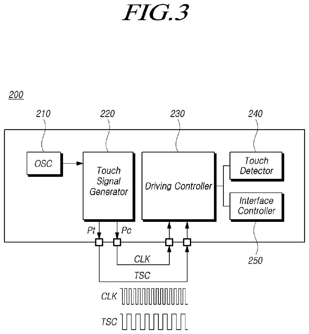
The present patent provides touch display devices, driving circuits, and driving methods that minimize the functionality of a micro control unit and reduce power consumption. This is achieved by allowing one or more combined integrated circuits to generate a touch sensing control signal and provide it to other combined circuits. Additionally, the patent provides methods to reduce power consumption of a touch power integrated circuit by using the touch sensing control signal generated by combined circuits as a load-free driving signal. These technical effects provide more efficient and effective touch display devices with reduced power consumption.

Problems solved by technology

However, the mounting of a separate touch panel on the touch display device leads the display device to be thick, and in turn, this implementation may limit a thin display device and have a disadvantage of allowing transmission efficiency of light to decrease while passing through the stacked touch panel, and production cost to increase.
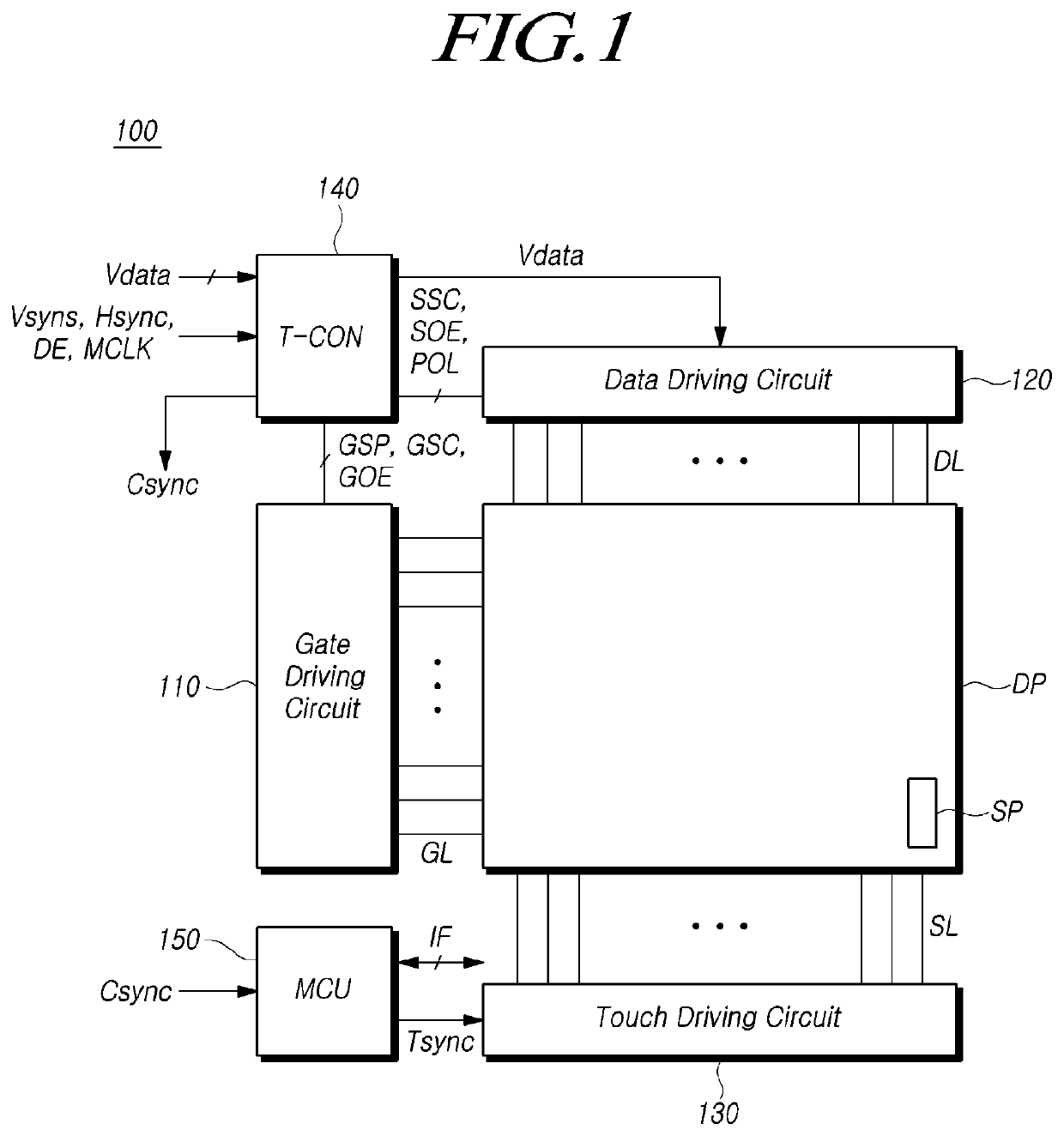
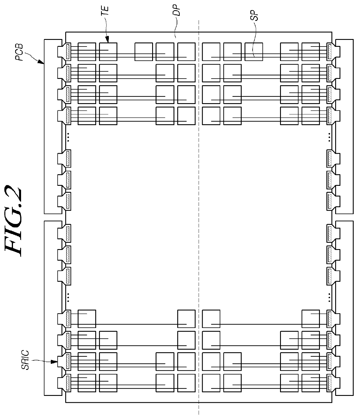
Like this, when the touch driving circuit determines the presence or absence of a touch based on a touch sensing signal provided from the external micro control unit, the micro control unit is needed to provide a touch sensing control signal to the combined integrated circuit SRIC to determine the presence or absence of a touch even when the touch display device is operated in a low power mode; therefore, there occurs a problem of allowing power consumption to increase in the low power mode.

Method used


Image

  • Touch Display Device, Driving Circuit and Driving Method Thereof
  • Touch Display Device, Driving Circuit and Driving Method Thereof
  • Touch Display Device, Driving Circuit and Driving Method Thereof

Examples


Embodiment Construction

[0035]In the following description of examples or embodiments of the present disclosure, reference will be made to the accompanying drawings in which it is shown by way of illustration specific examples or embodiments that can be implemented, and in which the same reference numerals and signs can be used to designate the same or like components even when they are shown in different accompanying drawings from one another. Further, in the following description of examples or embodiments of the present invention, detailed descriptions of well-known functions and components incorporated herein will be omitted when it is determined that the description may make the subject matter in some embodiments of the present invention rather unclear. The terms such as “including”, “having”, “containing”, “constituting”“make up of”, and “formed of” used herein are generally intended to allow other components to be added unless the terms are used with the term “only”. As used herein, singular forms a...


PUM


Abstract

Embodiments of the present disclosure relate to touch display devices, driving circuits, and driving methods, and more specifically, to a touch display device, a driving circuit, and a driving method for enabling the functionality of a micro control unit to be minimized and power consumption to be reduced by allowing one or more combined integrated circuits to generate a touch sensing control signal and provide the generated signal to a plurality of combined integrated circuits. Further, according to embodiments of the present disclosure, touch display devices, driving circuits, and driving methods are provided for enabling power consumption of a touch power integrated circuit to be reduced by using a touch sensing control signal generated by one or more combined integrated circuits as a load-free driving signal.

Description

CROSS-REFERENCE TO RELATED APPLICATION[0001]This application claims the priority benefit of Republic of Korea Patent Application No. 10-2019-0173903, filed on Dec. 24, 2019 in the Korean Intellectual Property Office, the disclosure of which is incorporated herein by reference in its entirety.BACKGROUND1. Technical Field[0002]The present disclosure relates to touch display devices, driving circuits, and driving methods.2. Description of the Related Art[0003]With the development of multimedia, demand for display devices has continued to increase. To meet such demand, flat-panel display devices, such as a liquid crystal display (LCD) device, a plasma display panel (PDP), and an organic light emitting display device, or the like, have been developed and utilized.[0004]Among such flat-panel display devices, the liquid crystal display device is widely used as a portable flat panel display device due to its excellent image quality, light weight, thinness, and low power consumption. In part...

Claims


Application Information

Patent Timeline
Patent Type & Authority Applications(United States)
IPC IPC(8): G06F3/041G09G3/36G06F3/044
CPCG06F3/0412G09G3/3674G09G3/3685G09G2310/0291G06F3/044G09G2310/08G09G2310/0297G09G3/3648G06F3/0416G09G2370/08G09G2330/021G06F3/0443G06F3/04184G06F1/3262H03K17/96
Inventor JO, YOUNGWOOKANG, HYEONGWON
Owner LG DISPLAY CO LTD
Features
  • Generate Ideas
  • Intellectual Property
  • Life Sciences
  • Materials
  • Tech Scout
  • Unparalleled Data Quality
  • Higher Quality Content
  • 60% Fewer Hallucinations
Learn More