Eureka AIR delivers breakthrough ideas for toughest innovation challenges, trusted by R&D personnel around the world.

Tool display rack with pivotable plate

Inactive Publication Date: 2013-01-03
CHANG CHI TSAI
View PDF12 Cites 0 Cited by
  • Summary
  • Abstract
  • Description
  • Claims
  • Application Information

AI Technical Summary

Benefits of technology

The present invention is a tool display rack that has a pivotal plate that can be opened out to hold tools. The rack has holes in the front to position the tools. The pivotal plate can be locked to the rack to keep the tools in place. This rack makes it easy to display and access tools.

Problems solved by technology

However, the packing material becomes obstacles for the observation from the customers and the paper boards cannot support the weight of the tools so that these tools are stacked and cannot be hanged on the wall.
The paper boards become soft and easily broken when they are in contact with humidity.

Method used


Image

  • Tool display rack with pivotable plate
  • Tool display rack with pivotable plate
  • Tool display rack with pivotable plate

Examples


Embodiment Construction

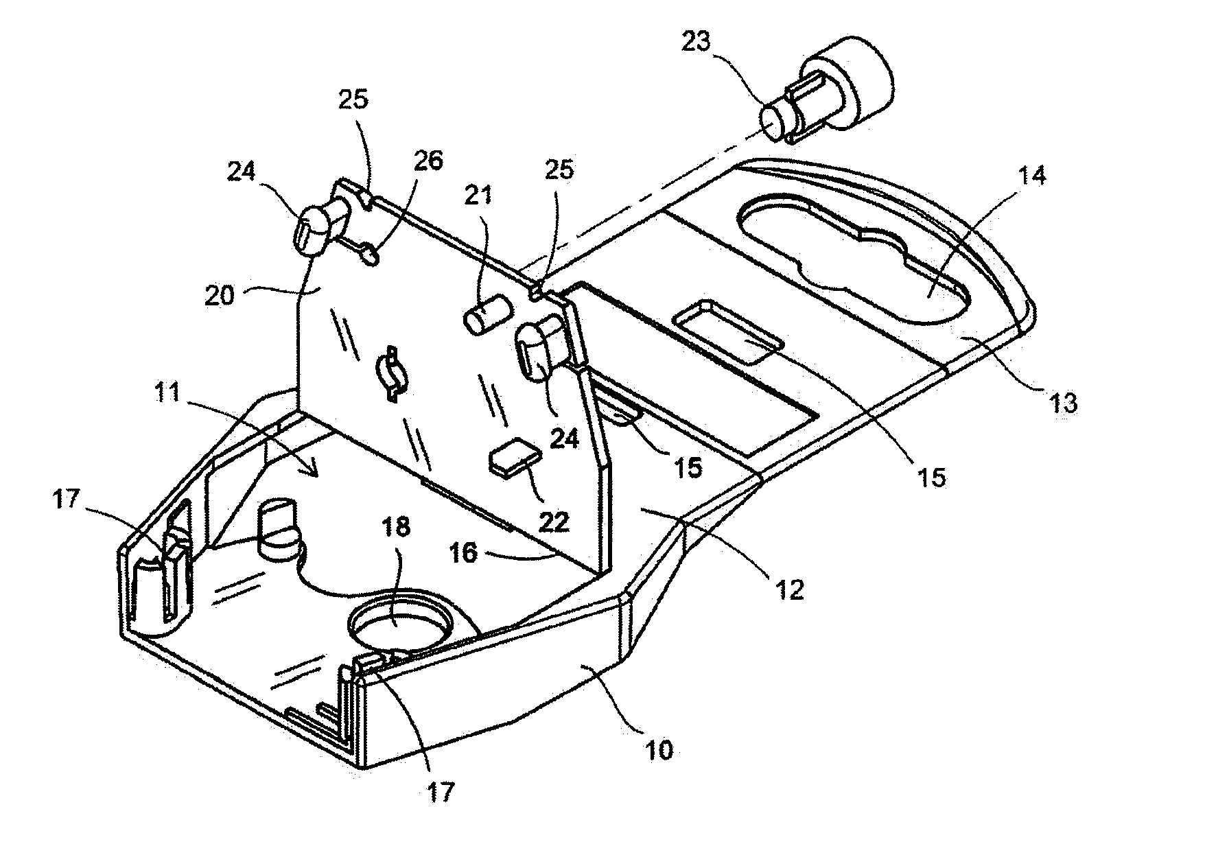
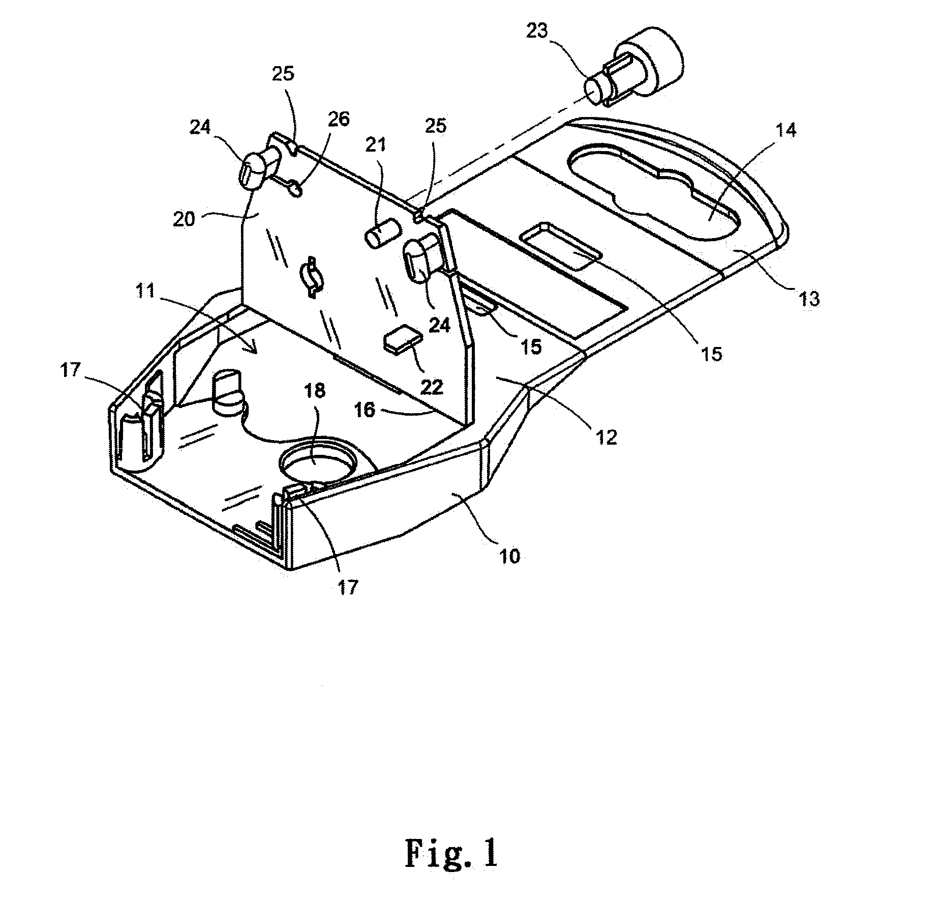
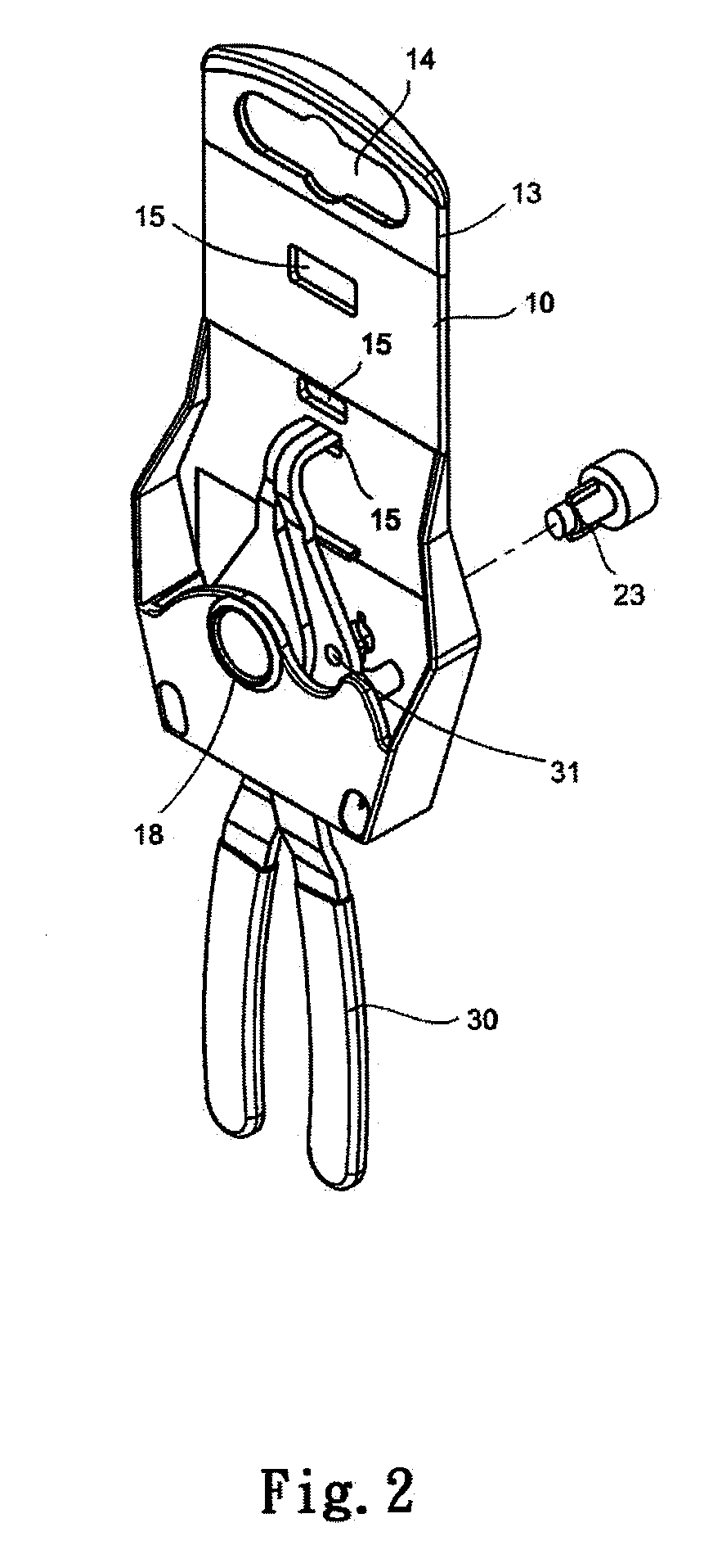
[0014]Referring to FIGS. 1 to 3, the tool display rack of the present invention comprises a body 10 having a box-shaped space 11 defined therein and the space 11 is partially defined by a back board 13. A hanging board 13 extends toward the top of the back board 13 and a hanging hole 14 is defined in the hanging board 13 for hanging the display rack on a wall. Multiple insertion holes 15 are defined in the extension (top portion) of the back board 12 and the insertion holes 15 have different sizes and shapes for positioning different tools. A folding line 16 is defined at the mediate portion of the back board 12 to form a pivotal plate 20 on the lower portion of the back board 12. The pivotal plate 20 has protrusions 21, positioning plates 19 or locking members 23 for positioning the tool 30. The pivotal plate 20 has two studs 24 extending from the inside thereof and the studs 24 are engaged with two locking slots 17 in the body 10. Multiple positioning holes 18 are defined in the f...


PUM


Abstract

A tool display rack includes a body having a box-shaped space defined therein and a pivotal plate is pivotably connected to the lower portion of the back board of the rack. The pivotal plate is pivotable outward to form a larger insertion entrance so as to accommodate the tool. Multiple positioning holes are defined in the front side of the body for positioning the tools. The pivotal plate has two studs extending from the inside thereof and the studs are engaged with two locking slots in the body so as to prevent the tool from dropping from the rack. When picking the tool, the studs are cut to pivot the pivotal plate and the tool can be picked out. The tool display rack is safe for the tool and suitable for display purpose.

Description

FIELD OF THE INVENTION[0001]The present invention relates to a tool display rack, and more particularly, to a safety display rack with a pivotal plate at the lower portion of the back board to form an insertion entrance through which the tool is inserted.BACKGROUND OF THE INVENTION[0002]The conventional tool display for display of small tools is designed to be hanged on a wall and most part of the tool is exposed for convenient observation by the customers. The tools such as pliers, screwdrivers or clip positioning tools, which have different length of handles and different sizes of curved portions, especially for the head portions with curvatures occupy a lot of space. Conventionally, the head portions are packed by paper boards and the whole tools are packed by bubbled sheets. The bubbled sheets are transparent so that the customers can see the tools and the tools are packed to prevent from dropping or being grabbed without permission. However, the packing material becomes obstacl...

Claims


Application Information

Patent Timeline
IPC IPC(8): A47F1/04
CPCB65D73/0071A47F5/0006
Inventor CHANG, CHI-TSAI
Owner CHANG CHI TSAI
Why Eureka
Eureka Blog
Learn More