Triangle insert with multiple cutting edges and milling cutter therefor

Active Publication Date: 2013-01-03
KENNAMETAL INC
View PDF22 Cites 32 Cited by
  • Summary
  • Abstract
  • Description
  • Claims
  • Application Information

AI Technical Summary

Benefits of technology

[0017]To increase the tool life and simplify producibility, the connecting edge can be rounded or chamfered. In

Problems solved by technology

In this case, however, the angles between the main cutting edge and the secondary cuttin

Method used


Image

  • Triangle insert with multiple cutting edges and milling cutter therefor
  • Triangle insert with multiple cutting edges and milling cutter therefor
  • Triangle insert with multiple cutting edges and milling cutter therefor

Examples


Example

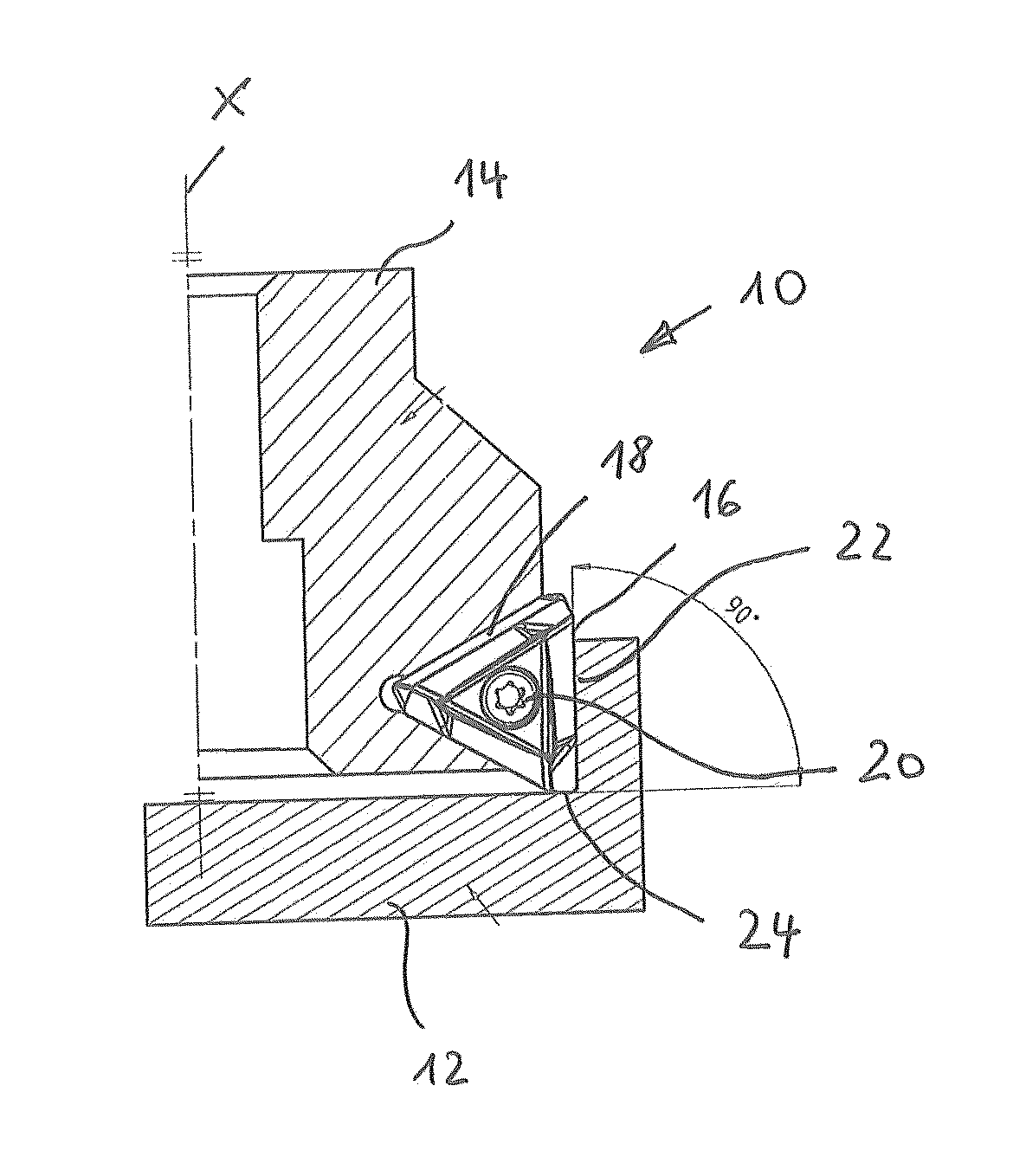
[0033]FIG. 1 shows a sectioned representation of a so-called surface corner milling cutter 10 in a radial section through its rotational axis X and through a workpiece 12. The milling cutter 10 comprises a driven tool shank 14, on the outer circumference of which several indexable inserts 16 are fastened. To this end, the shank 14 has corresponding pockets 18, in which the respective indexable inserts 16 are accommodated. The fastening of the indexable inserts 16 is effected, in particular, by means of screws 20 which pass through the center of the indexable inserts 16.

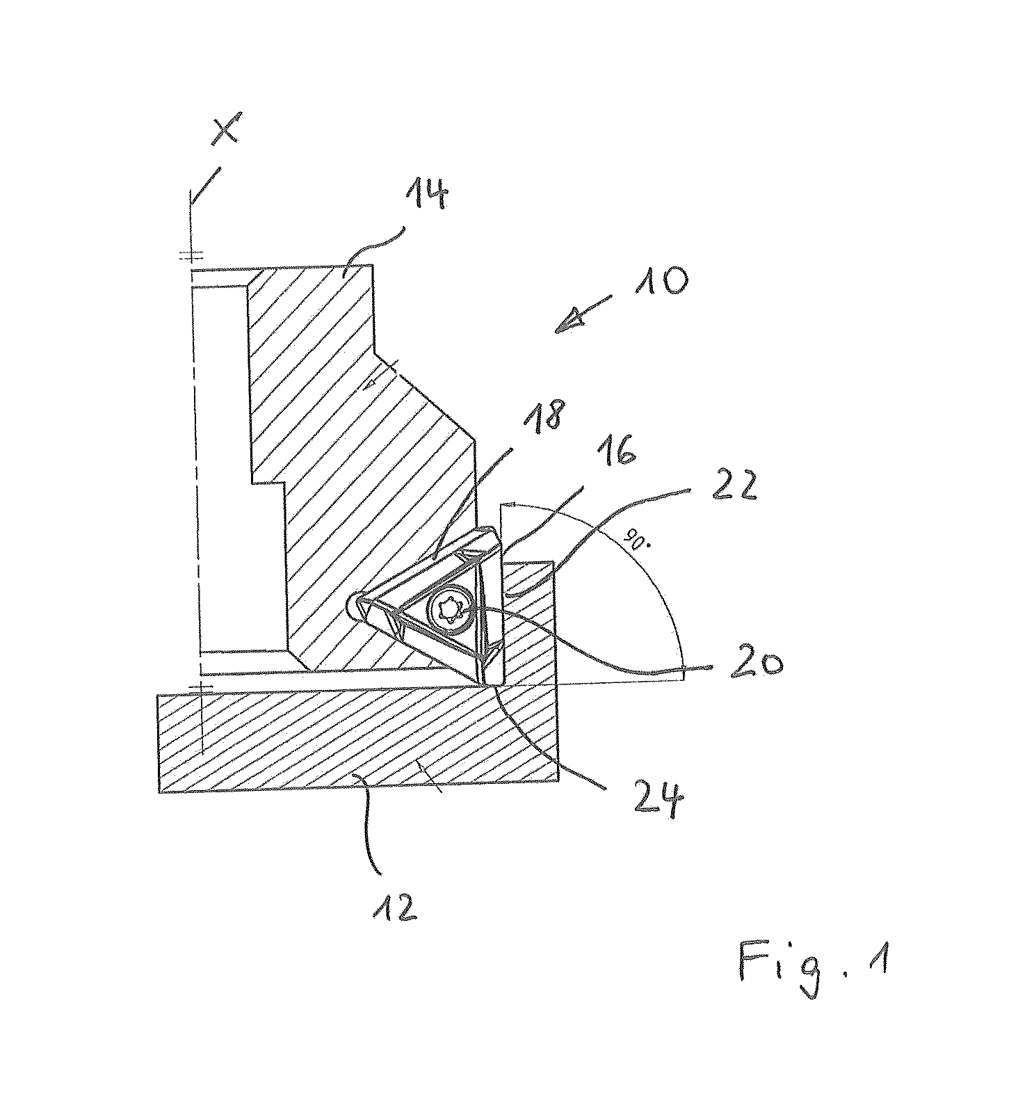
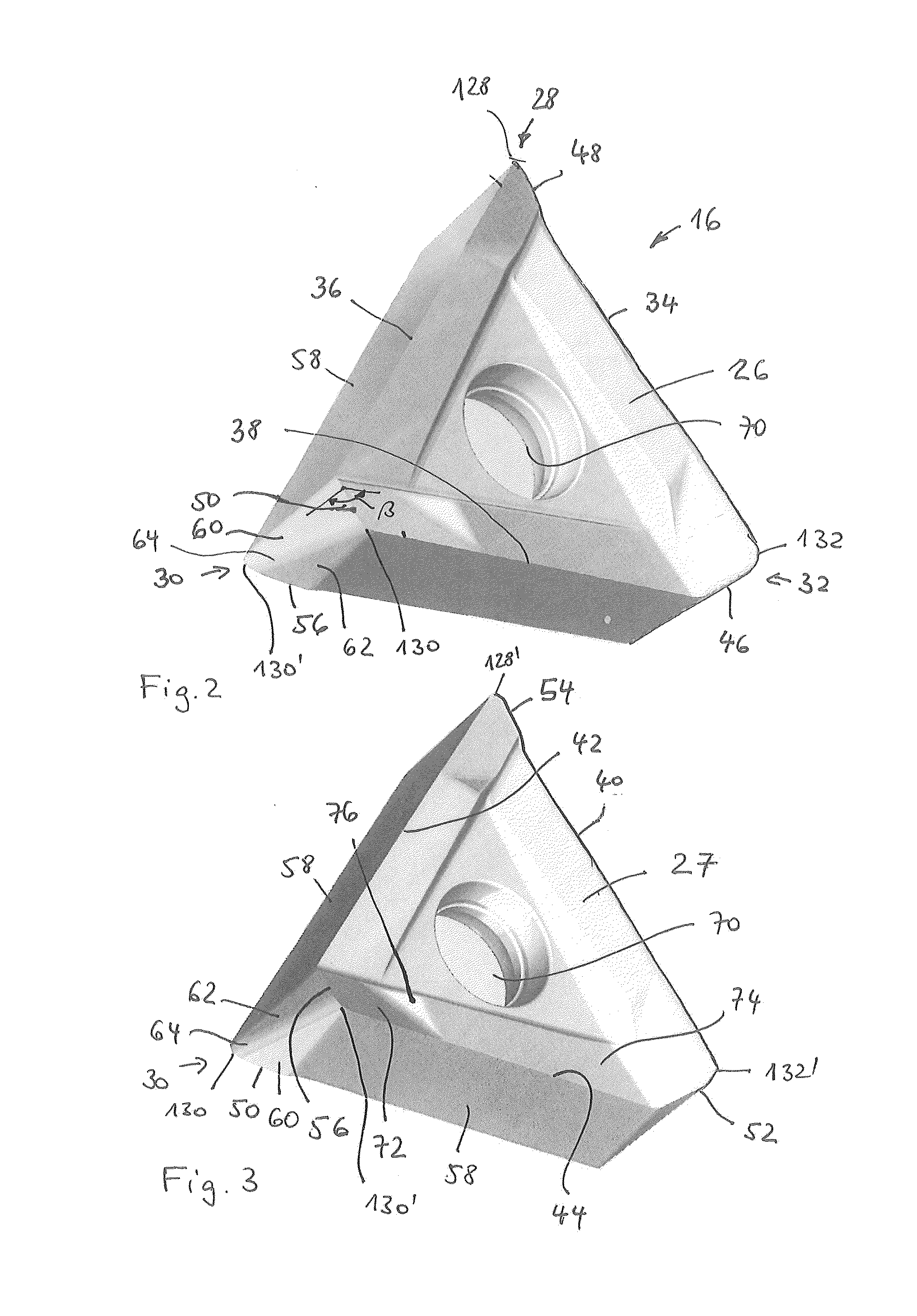
[0034]The indexable inserts 16 shown are triangular in shape and the cutting tips are in the form of a “T”, i.e. it is an equilateral triangle.

[0035]As can be seen in FIG. 1, the surface corner milling cutter 10 is a 90° surface corner milling cutter, i.e. the main cutting edges 22 which lie on the outer circumference of the milling cutter extend at approximately 90° with respect to the end face, shorter secondary cut...


PUM

PropertyMeasurementUnit
Angleaaaaaaaaaa
Angleaaaaaaaaaa
Angleaaaaaaaaaa

Abstract

An indexable insert (16) having a triangular shape with a top surface and a bottom surface (26), as well as a circumferential surface which connects said surfaces, has cutting edges around the corners (28-32). At least in the region of its edges on the top and bottom surface (26), the indexable insert (16) is identical such that all six cutting edges can be used for the same rotational cutting direction. The secondary cutting edges (46, 48, 50) adjoin two main cutting edges (34, 36, 38) and extend at different angles with respect to the same. Over and above this, a surface corner milling cutter with a corresponding indexable insert (16) is described.

Description

FIELD OF THE INVENTION[0001]The invention relates to an indexable insert, having a triangular shape having a top surface and a bottom surface as well as a circumferential surface which connects said surfaces, wherein cutting edges, which connect the circumferential surface to the top surface or the bottom surface, extend around the corners on each top surface and bottom surface.[0002]Over and above this, the invention relates to a surface corner milling cutter with a tool shank and at least one indexable insert fastened thereon.BACKGROUND OF THE INVENTION[0003]Triangular indexable inserts are used for turning and milling. The indexable inserts, in this case, have a main cutting edge and an adjoining secondary cutting edge, said cutting edges merging into each other in the region of one corner of the triangle. Such an indexable insert is known from U.S. Pat. No. 3,800,379. On its top surface along the longitudinal edges of the triangle, said cutting tip, which is used for turning, ha...

Claims


Application Information

Patent Timeline
IPC IPC(8): B23C5/20B23C5/02B23B27/16
CPCB23C5/06B23C5/207B23C2200/0477Y10T407/23Y10T407/1924Y10T407/235B23C2200/208B23C5/202
Inventor HAUSMANN, MARTINZASTROZYNSKI, JURGENSCHWANER, CARSTEN
Owner KENNAMETAL INC
Why Eureka
Try Eureka