Substrate cleaning apparatus and substrate cleaning method

a cleaning apparatus and substrate technology, applied in the direction of cleaning process and apparatus, suction cleaners, chemistry apparatus and processes, etc., can solve the problems of deteriorating device performance, physical damage to and collapse of the miniaturized device structur

Active Publication Date: 2013-01-10
TOKYO ELECTRON LTD +1
View PDF4 Cites 9 Cited by
  • Summary
  • Abstract
  • Description
  • Claims
  • Application Information

AI Technical Summary

Problems solved by technology

However, the conventional wet cleaning method has the following technical problems caused by miniaturization and complication of device structures formed on a wafer.
First problem: When a physical supplementary process such as an ultrasonic wave, two-fluid spray or the like is used, a miniaturized device structure may be physically damaged.
Second problem: The miniaturized device structure may be collapsed by surface tension of water.
Third problem: When a substrate may be dried after wet cleaning, a watermark is generated on the surface of the substrate whic...

Method used


Image

  • Substrate cleaning apparatus and substrate cleaning method
  • Substrate cleaning apparatus and substrate cleaning method
  • Substrate cleaning apparatus and substrate cleaning method

Examples


first modification

[0074](First Modification)

[0075]A substrate cleaning apparatus in accordance with a first modification of the above-described embodiment is configured to transfer cleaning target objects decomposed by spraying clusters of cleaning agents to the first to the third suction unit by a transfer gas. The substrate cleaning apparatus in accordance with the first modification is the same as that of the above-described embodiment except for the configurations of the first to the third nozzle and the transfer gas, so that only the differences will be described hereinafter.

[0076]FIG. 11 is a side cross sectional view schematically showing a configuration example of a substrate cleaning apparatus in accordance with this first modification. FIG. 12 is a side cross sectional view schematically showing a configuration example of a cluster spraying head 203 in accordance with the first modification. A first to a third nozzle 231c to 233c of the cluster spraying head 203 of the substrate cleaning ap...

second modification

[0082](Second Modification)

[0083]In a substrate cleaning apparatus in accordance with a second modification of the above-described embodiment, a wafer is moved while a cluster spraying head is fixed to a processing chamber. The substrate cleaning apparatus in accordance with the second modification is the same as that of the above-described embodiment except for such configuration, so that only the differences will be described hereinafter.

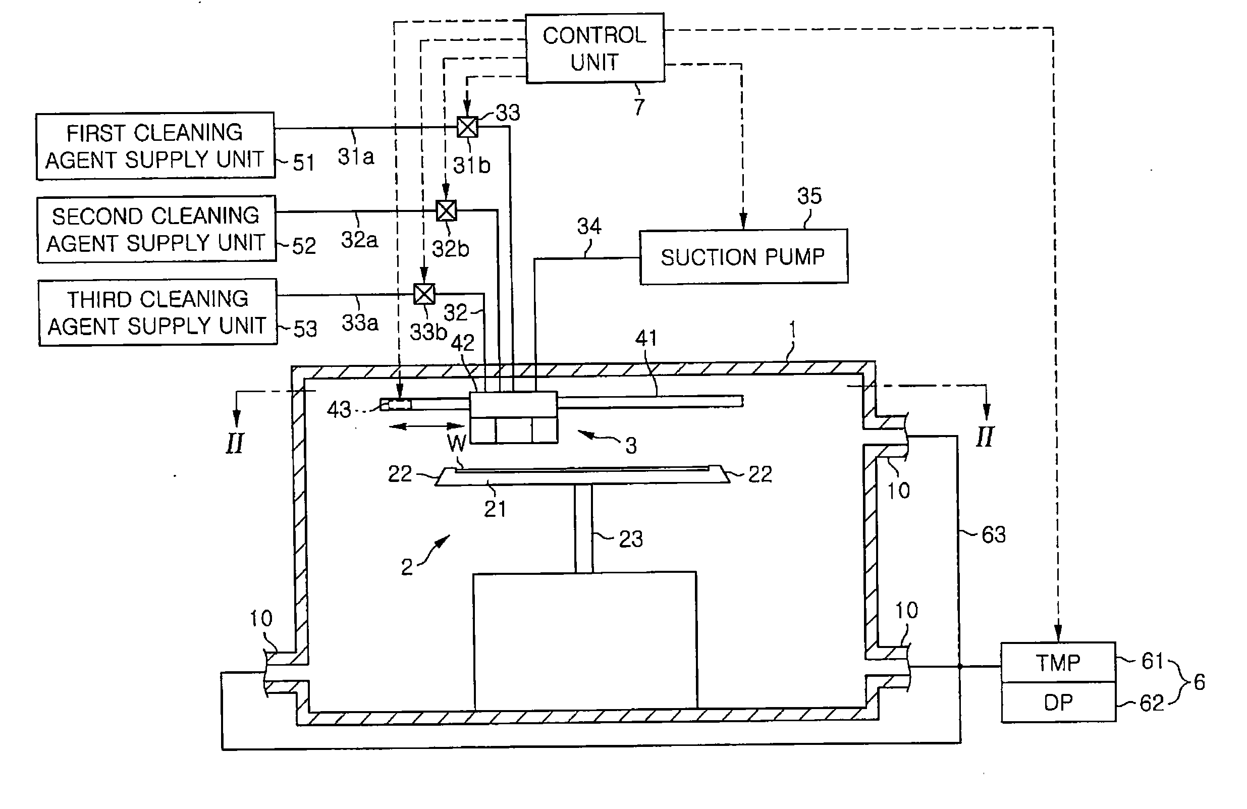
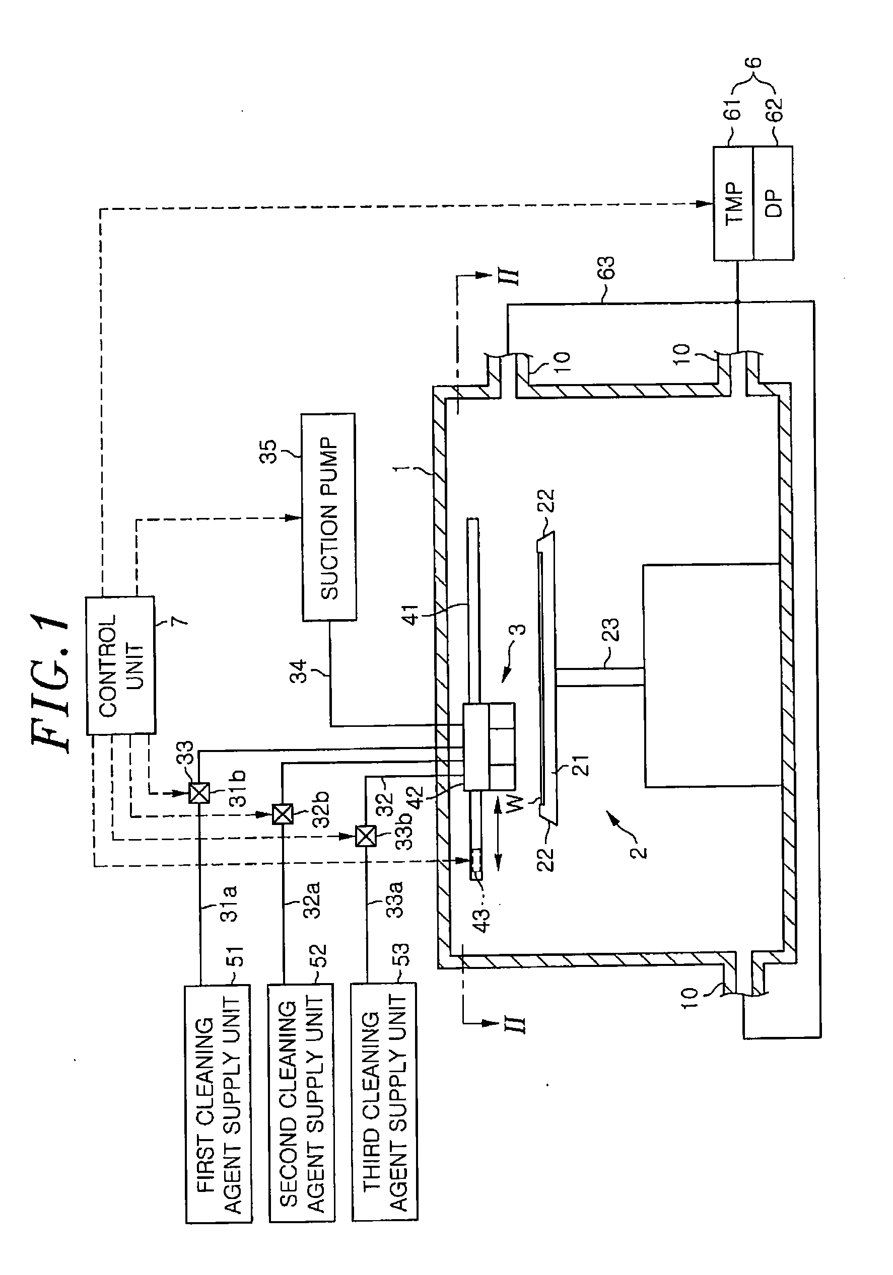
[0084]FIG. 13 is a side cross sectional view schematically showing a configuration example of a substrate cleaning apparatus in accordance with the second modification. The substrate cleaning apparatus in accordance with the second modification includes a processing chamber 301 in which the cluster spraying head 3 is fixed to a substantially central portion of a ceiling plate thereof. Further, a driving unit 343 for moving the table portion 21 in a horizontal direction is provided at a bottom portion of the processing chamber 301. The driving unit...

first embodiment

[0085]In the second modification, the cluster spraying head 3 is fixed to the ceiling plate of the processing chamber 301. Therefore, it is possible to reduce the possibility in which the wafer W is contaminated by particles from the driving unit 343, compared to the


PUM


Abstract

A substrate cleaning device is capable of removing more diverse contaminants from substrates than ultra-low temperature aerosol ejection, while avoiding technical problems inherent to wet cleaning, such as micro-roughness, watermarks, loss of substrate material and destruction of the device structure. A substrate cleaning device for cleaning wafers to which cleaning target objects have adhered includes a cluster spraying unit which sprays the wafer with one or more types of clusters formed of cleaning preparation molecules agglomerated together, a suction unit which sucks the cleaning target objects separated by spraying the clusters of the cleaning agent molecules; and a unit for moving the wafer and the cluster spraying unit relative to the one another along the surface of the wafer W to which the cleaning target objects have adhered.

Description

[0001]This application is a Continuation Application of PCT International Application No. PCT / JP2011 / 056167 filed on Mar. 16, 2011, which designated the United States.FIELD OF THE INVENTION[0002]The present invention relates to a substrate cleaning apparatus and a substrate cleaning method for cleaning a substrate to which cleaning target objects have adhered.BACKGROUND OF THE INVENTION[0003]Wet cleaning using water is employed for wafer cleaning performed after various substrate processes. Japanese Patent Application Publication No. 2000-325894 (JP2000-325894A) describes a substrate cleaning apparatus including a rotation unit for rotating a wafer, a line-shaped ejection nozzle for ejecting cleaning liquid to a wafer in a line shape, and a moving unit for moving the line-shaped ejection nozzle along the wafer. In accordance with the substrate cleaning apparatus described in JP2000-325894A, even a large-sized wafer can be cleaned by cleaning water while ensuring high throughput and ...

Claims


Application Information

Patent Timeline
IPC IPC(8): B08B7/00
CPCH01L21/67051H01L21/31133H01L21/0206H01L21/02052H01L21/302
Inventor DOBASHI, KAZUYAFUSE, TAKASHI
Owner TOKYO ELECTRON LTD
Why Eureka
Try Eureka