

Solar roofing system
a solar roof and solar energy technology, applied in the field of solar roof systems, can solve the problems of adding significant cost to roof replacement, labor-intensive installation of typical building applied photovoltaic (bapv) and building integrated photovoltaic (bipv) systems,
- Summary
- Abstract
- Description
- Claims
- Application Information
AI Technical Summary
Benefits of technology
Problems solved by technology
Method used
Image

Examples
first embodiment
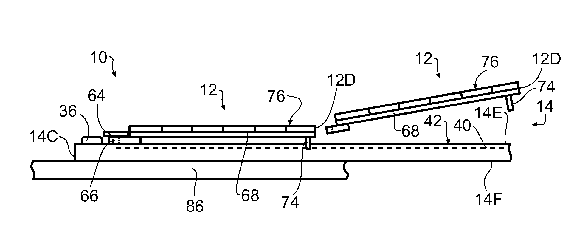
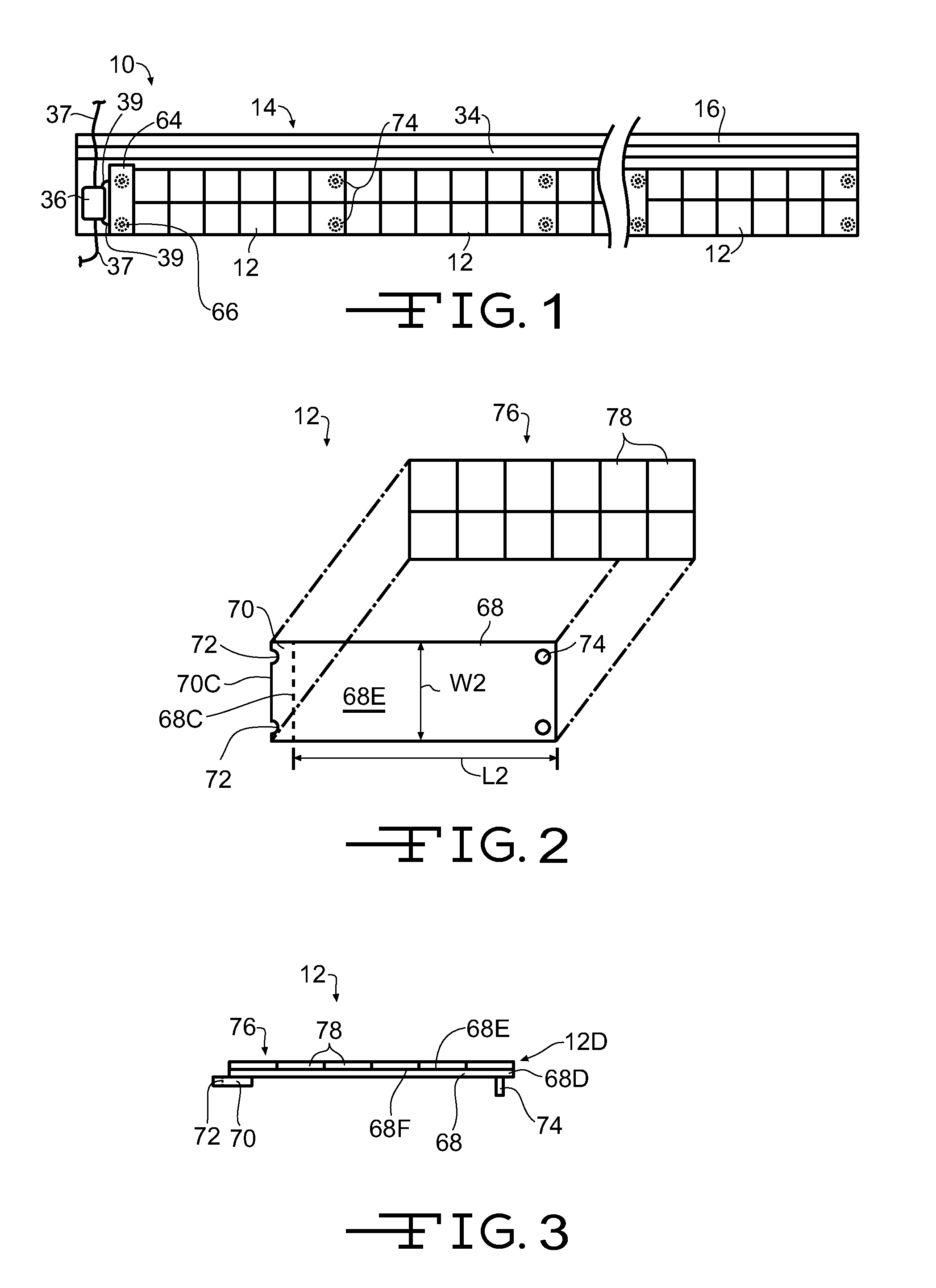
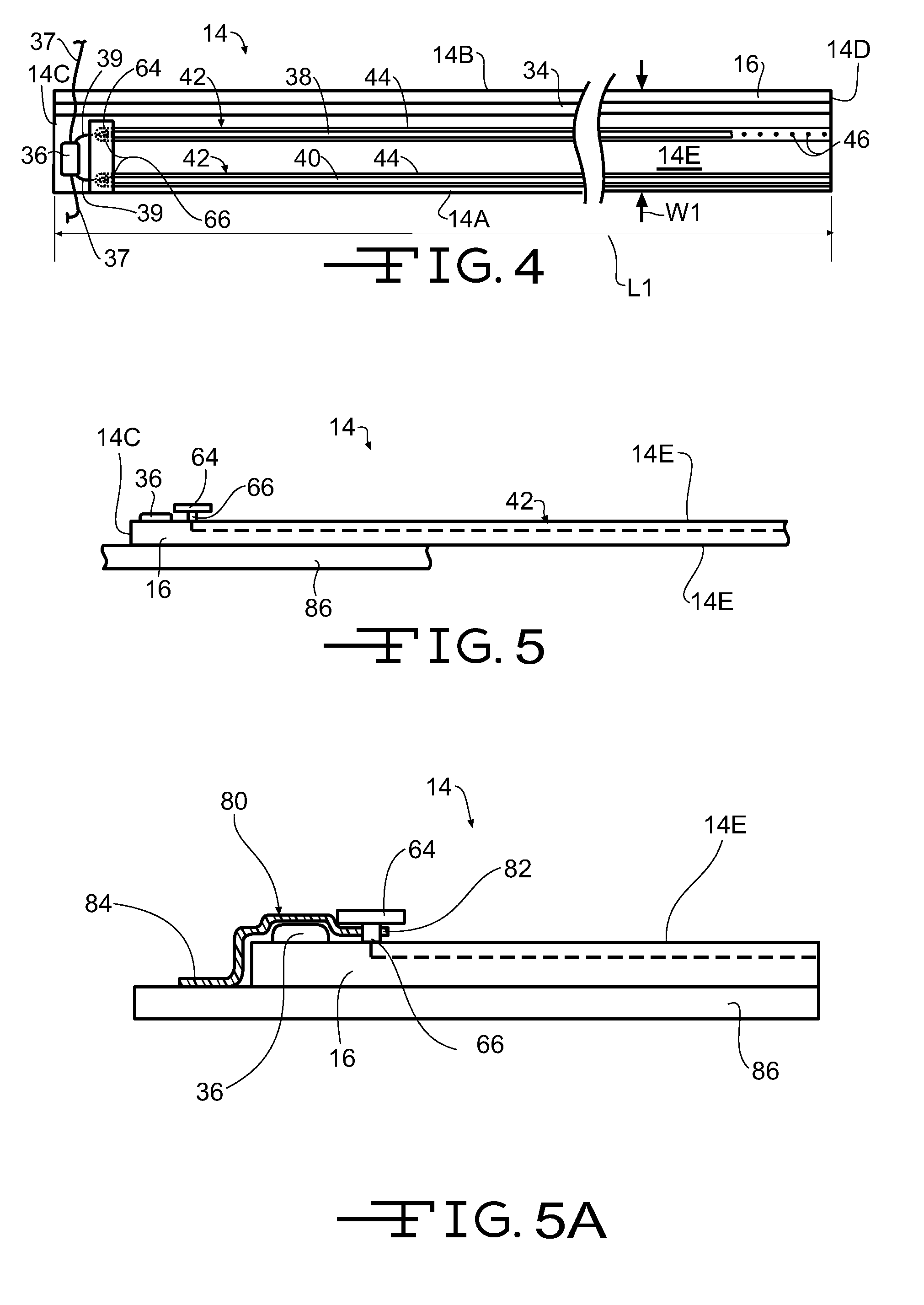
[0032]Referring now to FIGS. 1 through 5, a photovoltaic or solar roofing shingle assembly is shown generally at 10. In the illustrated embodiment, the solar roofing shingle assembly 10 includes a plurality of photovoltaic or solar roofing shingles 12 attached to a photovoltaic or solar roofing shingle attachment panel 14, hereinafter referred to as the attachment panel 14. The attachment panel 14 has a leading edge 14A, a trailing edge 14B, first end 14C (left end when viewing FIG. 4), a second end 14D (right end when viewing FIG. 4), a first surface 14E (the upwardly facing surface when installed on a roof), and a second surface or back side 14F, opposite the first surface 14E.
[0033]The attachment panel 14 includes a substrate 16, shown with exaggerated thickness for clarity. In a first embodiment, the substrate 16 is formed from glass reinforced, polymer modified asphalt, such as is used to form a roofing shingle. In other embodiments, the substrate 16 may be formed from polymers...
second embodiment
[0035]In the embodiment illustrated in FIGS. 4 and 5, the attachment panel 14 is shown as including a single layer of the substrate 16. Alternatively, the attachment panel 14 may include two layers of the substrate 16. As shown in FIG. 6, the attachment panel is shown at 18 and includes a first substrate layer 20 defining the first surface 20E (the upwardly facing surface when installed on a roof). A second substrate layer 22 is substantially the same length as the first substrate layer 20 and is bonded to the backside 20F of the first substrate layer 20. Alternatively, the attachment panel 18 may include more than two layers of the substrate.
third embodiment
[0036]Referring to FIG. 7, the attachment panel is shown at 24 and includes the first substrate layer 20 defining the first surface 20E. A second substrate layer 26 is bonded to the backside 20F of the first substrate layer 20. The second substrate layer 26 is longer than the first substrate layer 20, such that a first end 26C (left end when viewing FIG. 7), and a second end 26D (right end when viewing FIG. 7), of the second substrate layer 26 each extend outward of a first end 20C and a second end 20D of the first substrate layer 20, respectively, and define mounting members 28. In the illustrated embodiment, the first end 26C and the second end 26D may extend outward of the first end 20C and the second end 20D of the first substrate layer 20, respectively, by about 4.0 inches. Alternatively, the first end 26C and the second end 26D may extend outward of the first end 20C and the second end 20D of the first substrate layer 20 a distance within the range of about 1.0 inch to about 8...
PUM
 Abstract
Description
Claims
Application Information