
Method of removing liquid from a barrier structure

a barrier structure and liquid technology, applied in the direction of cleaning processes and utensils, electrical utensils, chemical instruments and processes, etc., can solve the problem that spray may not effectively reach the center or the outer periphery, and achieve the effect of rapid, efficient rinsing and/or drying of wetted surfaces, and fast and efficien

Inactive Publication Date: 2013-02-07
TEL EPION
View PDF0 Cites 6 Cited by
  • Summary
  • Abstract
  • Description
  • Claims
  • Application Information

AI Technical Summary

Benefits of technology

The present invention provides a tool for treating microelectronic workpieces with various treatment materials. The invention allows for rapid, efficient rinsing and drying of wetted surfaces, particularly on the lower surface of moveable barrier structures. The invention also minimizes thermal effects between a spraying mechanism and the barrier plate, allowing for separate components that can be independently fabricated and accommodating differences in thermal expansion. Furthermore, the invention provides a simple way to help contain mists and prevent sprayed material from escaping the process chamber. These technical effects are useful in the field of microelectronic workpiece treatment.

Problems solved by technology

It has been observed that the nozzle footprint through which a spray is created may not match the on-workpiece footprint of the spray when the spray reaches the workpiece.
Thus, if the footprint of the nozzle openings merely span from the workpiece center to the outer periphery, the resultant spray may not actually effectively reach the center or the outer periphery, depending on spin speeds, exhaust flow rates, spraybar height above the workpiece, and / or the like.

Method used


Image

  • Method of removing liquid from a barrier structure
  • Method of removing liquid from a barrier structure
  • Method of removing liquid from a barrier structure

Examples


Embodiment Construction

[0072]The embodiments of the present invention described below are not intended to be exhaustive or to limit the invention to the precise forms disclosed in the following detailed description. Rather the embodiments are chosen and described so that others skilled in the art may appreciate and understand the principles and practices of the present invention. While the present invention will be described in the specific context of fluid based microelectronic substrate cleaning systems, the principles of the invention are applicable to other microelectronic processing systems as well.

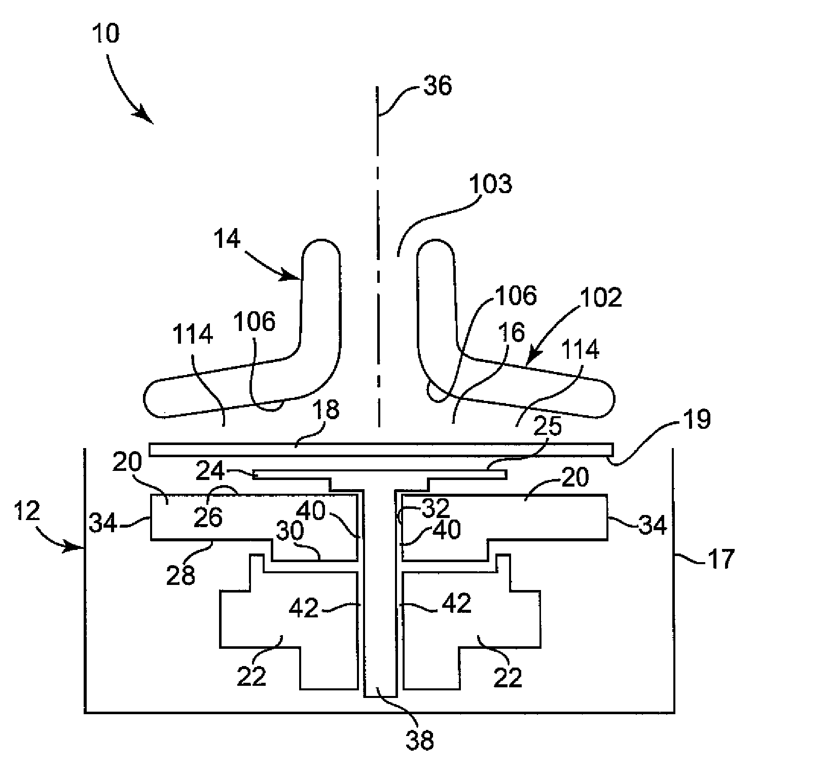
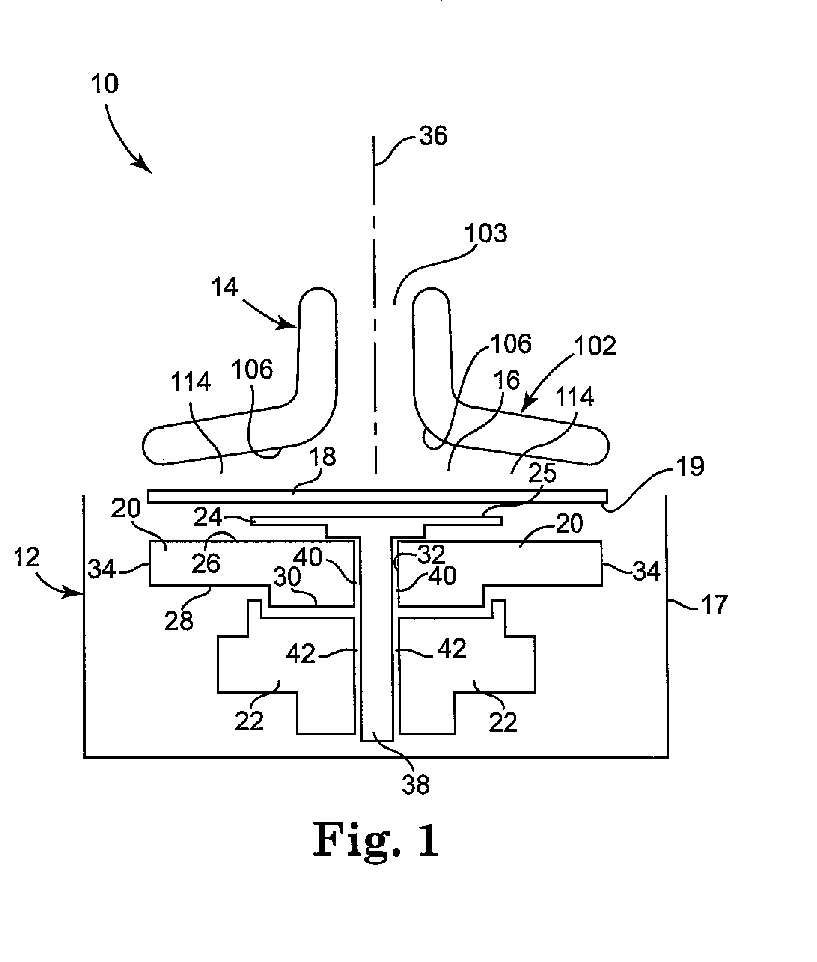
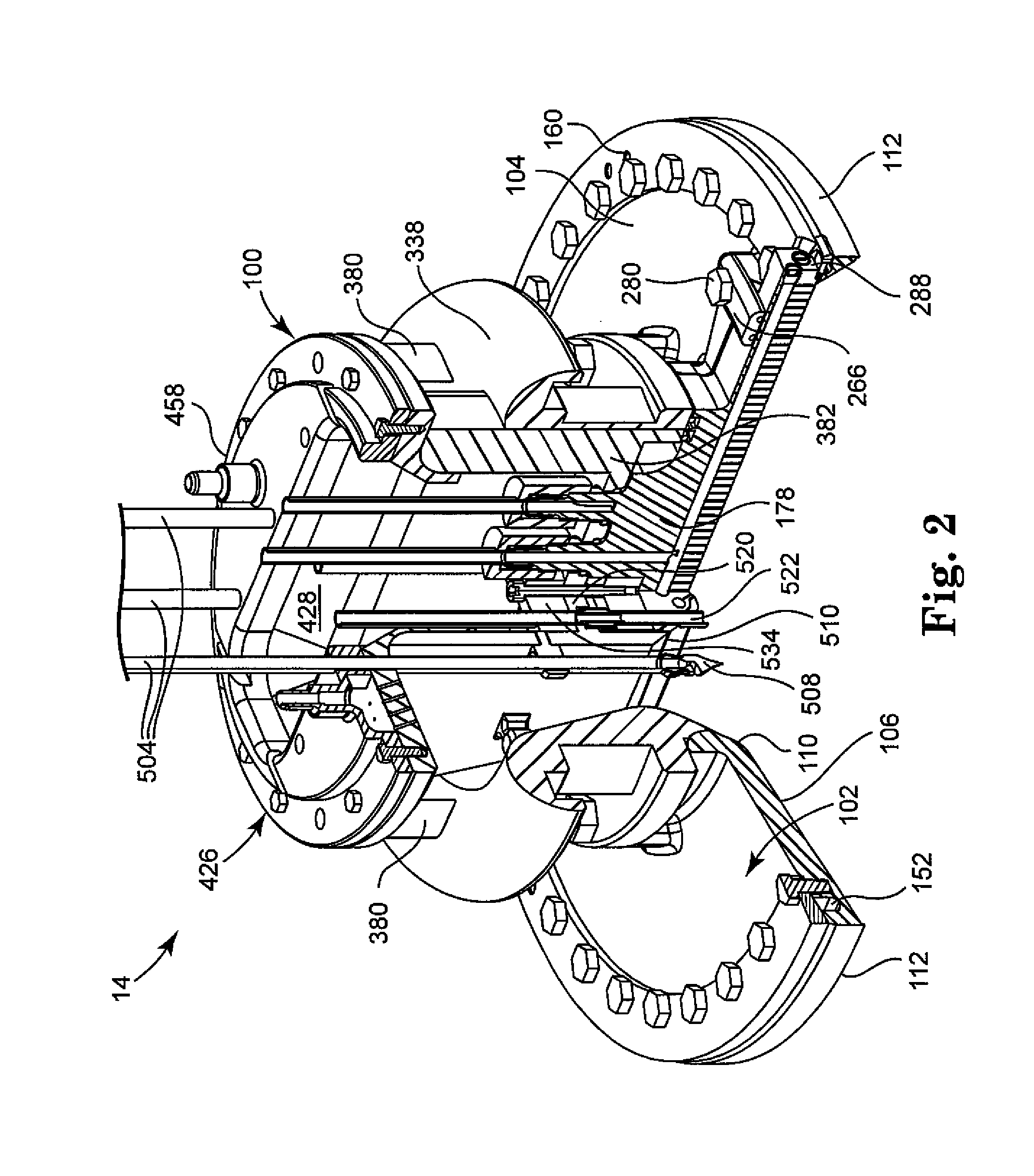
[0073]FIGS. 1 through 37 show an illustrative tool 10 that incorporates principles of the present invention. For purposes of illustration, tool 10 is of the type in which a single workpiece 18 is housed in the tool 10 at any one time and subjected to one or more treatments in which liquid(s), gas(es), and / or other processing media are caused to contact the workpiece 18. In the microelectronics industry, fo...


PUM

PropertyMeasurementUnit
diameteraaaaaaaaaa
diameteraaaaaaaaaa
diameteraaaaaaaaaa

Abstract

The present invention provides a tool for treating microelectronic workpieces with one or more treatment materials, including liquids, gases, fluidized solids, dispersions, combinations of these, and the like.

Description

PRIORITY CLAIM[0001]This application is a divisional of patent application Ser. No. 11 / 820,709, filed Jun. 20, 2007, now U.S. Publication No. 2008-0008834, and entitled BARRIER STRUCTURE AND NOZZLE DEVICE FOR USE IN TOOLS USED TO PROCESS MICROELECTRONIC WORKPIECES WITH ONE OR MORE TREATMENT FLUIDS, wherein the respective entirety of said nonprovisional application is incorporated herein by reference and wherein said nonprovisional application claims priority under 35 USC §119(e) from United States Provisional Patent Applications having serial number 60 / 819,133, filed on Jul. 7, 2006 and titled BARRIER STRUCTURE AND NOZZLE DEVICE FOR USE IN TOOLS USED TO PROCESS MICROELECTRONIC WORKPIECES WITH ONE OR MORE TREATMENT FLUIDS, wherein the respective entirety of said provisional patent application is incorporated herein by reference.FIELD OF THE INVENTION[0002]The present invention relates to barrier plates and dispense assemblies for tools used to process microelectronic substrates with ...

Claims


Application Information

Patent Timeline
Patent Type & Authority Applications(United States)
IPC IPC(8): B08B1/00
CPCH01L21/67051H01L21/67011B05B1/28H01L21/00
Inventor COLLINS, JIMMY D.DEKRAKER, DAVID P.GAST, TRACY A.ROSE, ALAN D.
Owner TEL EPION
Learn More