Split Control Unit

a split control and unit technology, applied in the direction of lift valves, multi-way valves, plug valves, etc., can solve the problems of difficult control of the split flow of fuel between two manifolds in the fuel distribution system of the turbine engine, difficult control of valves, and high cost of valves,

Active Publication Date: 2013-02-21
WOODWARD GOVERNOR CO
View PDF6 Cites 43 Cited by
  • Summary
  • Abstract
  • Description
  • Claims
  • Application Information

AI Technical Summary

Benefits of technology

[0015]In further embodiments, in addition to metering fuel flow split, the metering control device is configured to control the pressure difference between the manifolds while passing all flow down the primary manifold. This results in the ability to control cooling flow in the

Problems solved by technology

Controlling the fuel flow split between two manifolds in a turbine engine fuel distribution system can be difficult due to a variety of constraints.
Those constraints may include the need for cooling flow at all operating conditions, the need to have enrichment zones on the engine, and the need to have variable, controllable flow split ov

Method used


Image

  • Split Control Unit
  • Split Control Unit
  • Split Control Unit

Examples


Embodiment Construction

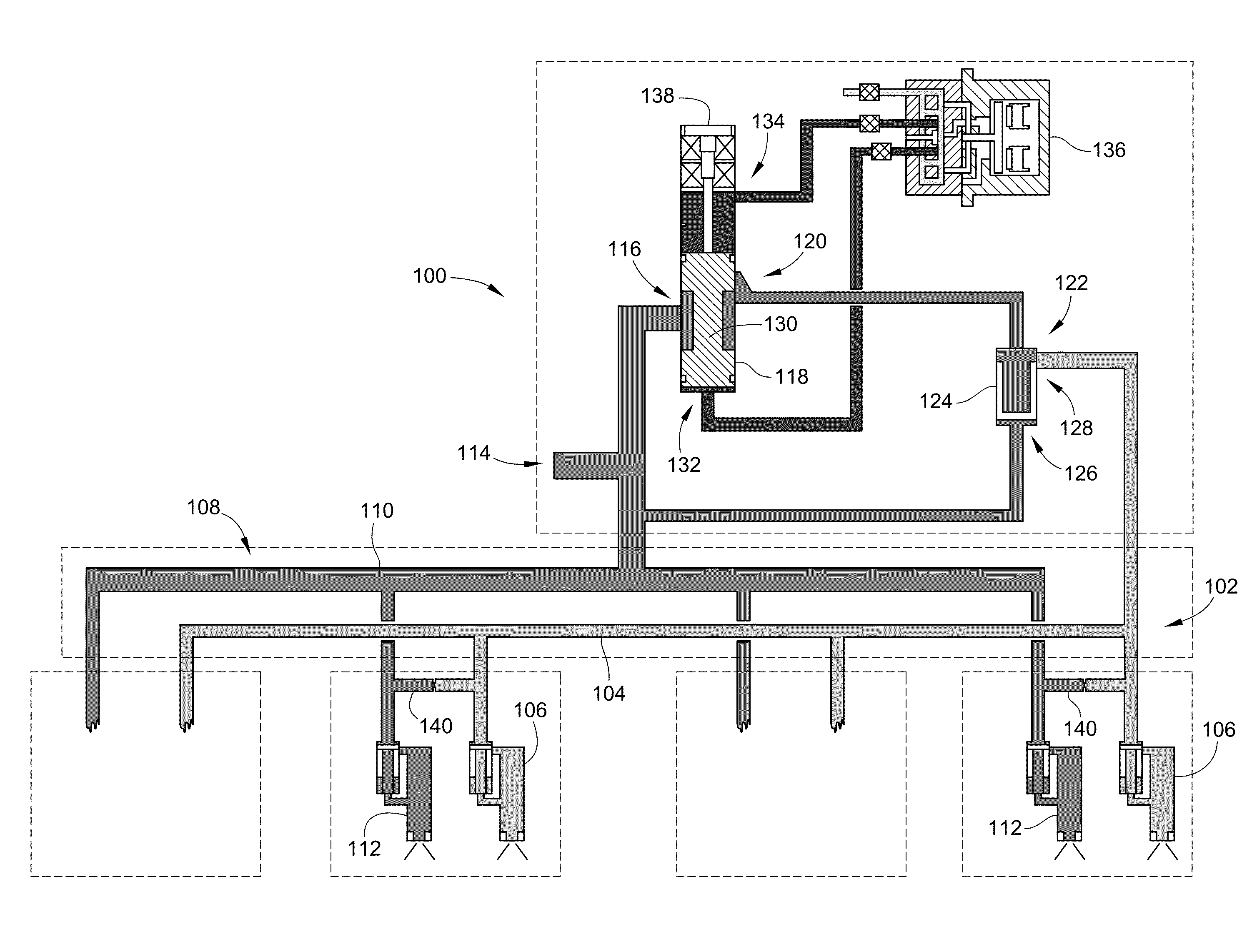
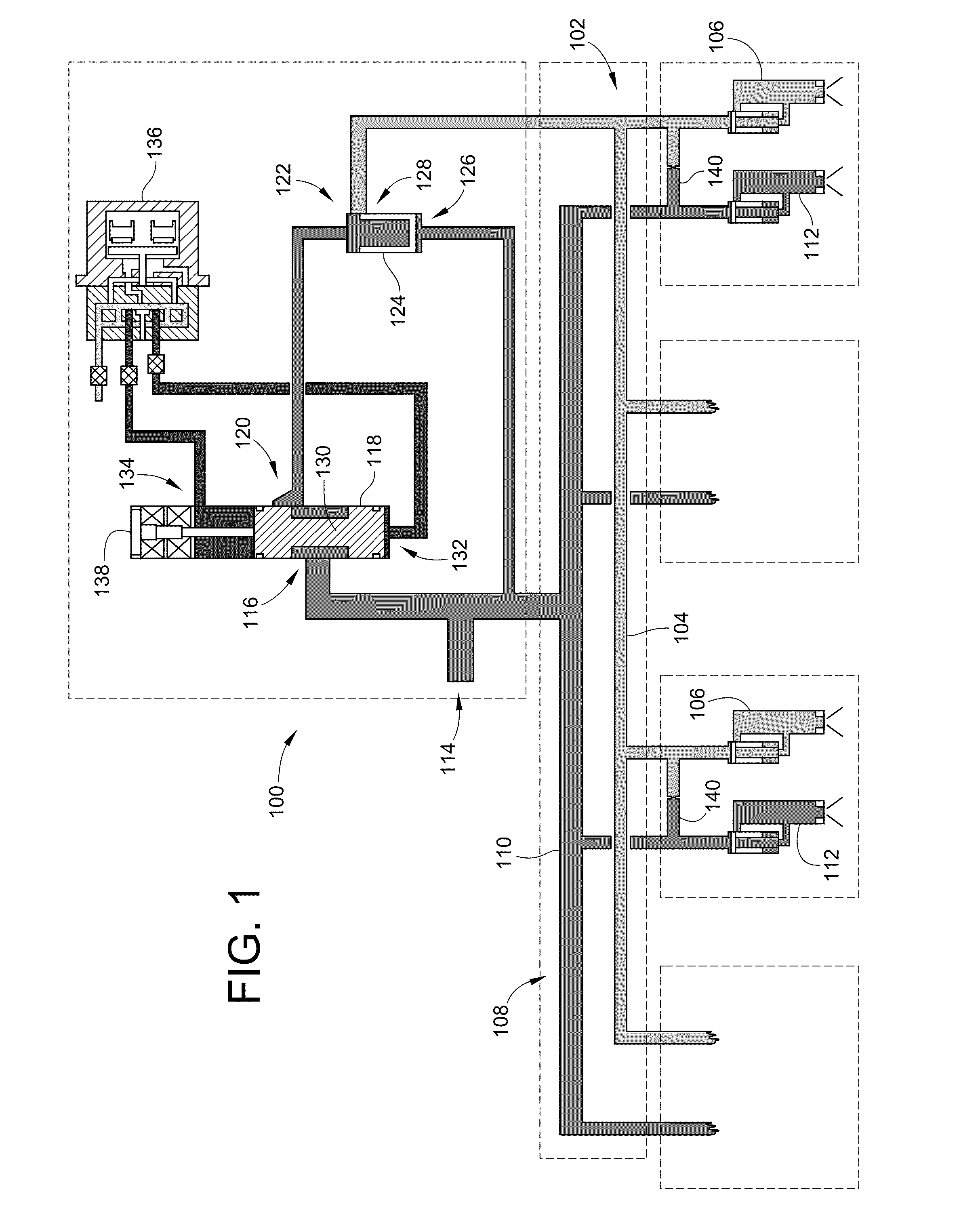
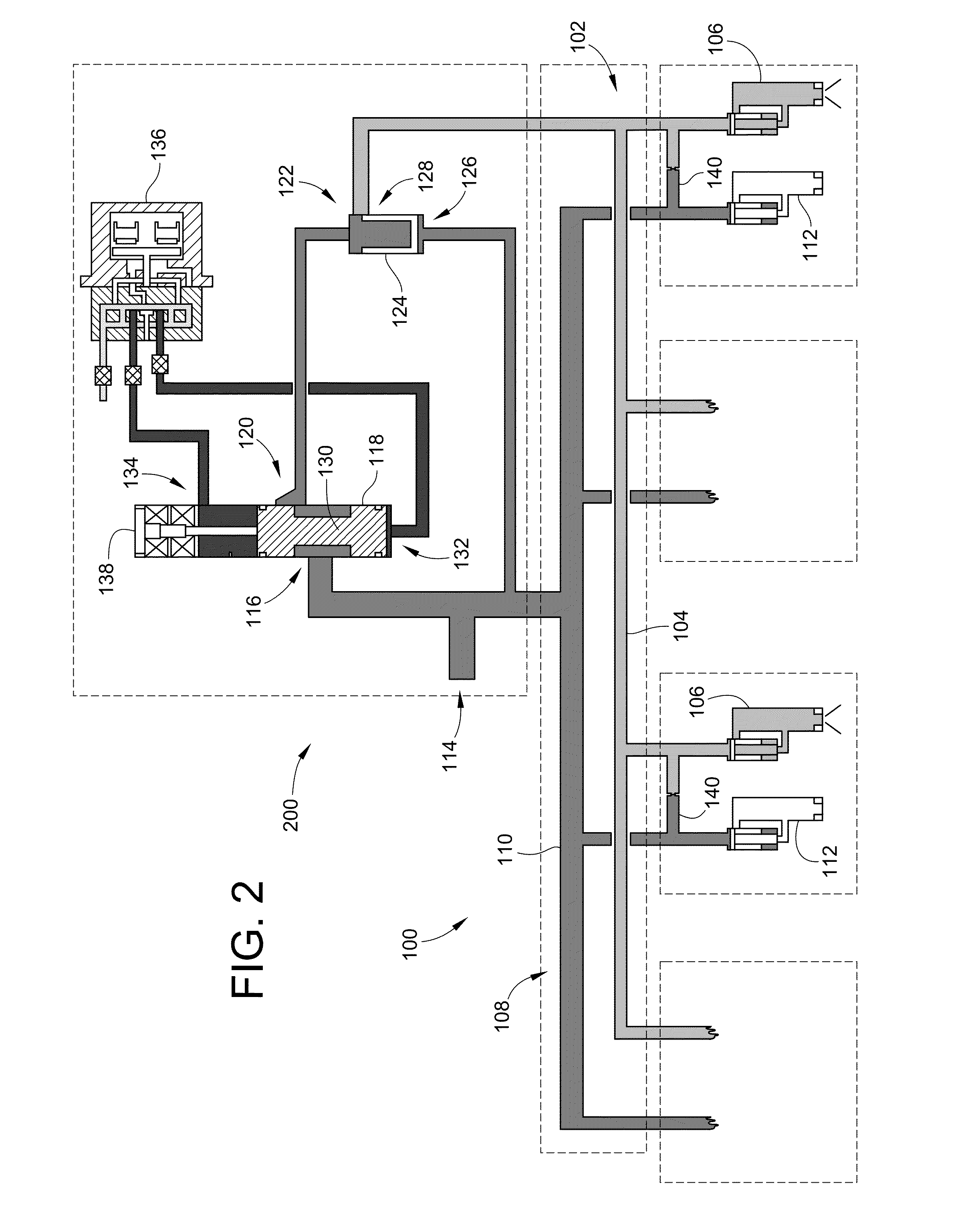
[0026]Embodiments of a split control unit are disclosed herein. Typically, these embodiments work in conjunctions with nozzle valving that requires flow regulation to two or more combustion zones. However, it is contemplated that embodiments of the split control unit could be employed in systems having more than two fuel manifolds. In particular embodiments, the nozzle valving may include a bleed orifice between the two inlet fittings to allow continuous flow in both fuel manifolds regardless of operating condition.

[0027]Embodiments of the invention allow for the control of two flow circuits to a plurality of fuel nozzles, through independent primary and secondary manifolds. In particular embodiments, the system controls the flow split by metering a portion of the total flow in one of the fuel manifolds. The remainder of the total flow is passed down the other manifold. This method of fuel flow split control is insensitive to manifold pressures, thus fuel flow split accuracy is not ...


PUM


Abstract

A split control unit in a distributed flow unit includes a flow inlet configured to receive a fuel flow, a first manifold having flow lines to supply fuel to one or more primary nozzles, and a second manifold having flow lines to supply fuel to one or more secondary nozzles. In an embodiment, the second manifold is in fluid communication with the flow inlet. A metering valve has a first port in fluid communication with the flow inlet and with the second manifold. The metering valve is configured to supply a metered fuel flow to the first manifold. A flow passage is in fluid communication with, and runs between, a flow line of the first manifold and a flow line of the second manifold to allow for a continuous cooling flow in the second manifold when all of the one or more secondary nozzles are closed.

Description

CROSS-REFERENCE TO RELATED PATENT APPLICATIONS[0001]This patent application claims the benefit of U.S. Provisional Patent Application No. 61 / 525,420, filed Aug. 19, 2011, the entire teachings and disclosure of which are incorporated herein by reference thereto.FIELD OF THE INVENTION[0002]This invention generally relates to fuel flow distribution systems and to flow control systems therefor.BACKGROUND OF THE INVENTION[0003]Controlling the fuel flow split between two manifolds in a turbine engine fuel distribution system can be difficult due to a variety of constraints. Those constraints may include the need for cooling flow at all operating conditions, the need to have enrichment zones on the engine, and the need to have variable, controllable flow split over a range of total engine fuel flow rates.[0004]Some conventional fuel distribution systems inventions have addressed these constraints with two complicated valves in each nozzle, configured to provide discrete flow split levels. ...

Claims


Application Information

Patent Timeline
IPC IPC(8): F16K11/00
CPCF01D5/147F01D5/148F23K5/06F23R3/34F05D2230/51F05D2230/80F02C9/34F23K2203/105F23R2900/00004F05D2250/90Y02T50/673F02C7/228F02C9/263F05D2240/304Y02T50/60Y10T137/0318Y10T137/877F02C1/00F02C9/26F02C9/28F02G3/00F16K11/00
Inventor SNODGRASS, BRETT JAYCARSON, CHARLIEBAKER, CARTHEL C.GARRY, MICHAEL P.
Owner WOODWARD GOVERNOR CO
Why Eureka
Try Eureka