
CRT Light Pen Interface for Flat Panel Displays

a flat panel display and light pen technology, applied in the field of flat panel display light pen interfaces, can solve the problems of cost, reliability, and significant limitations of alternative user interfaces, and achieve the effects of reducing the cost of alternative user interfaces, and improving the serviceability of users

Active Publication Date: 2013-02-21
PLASMABILITY
View PDF2 Cites 9 Cited by
  • Summary
  • Abstract
  • Description
  • Claims
  • Application Information

AI Technical Summary

Benefits of technology

The patent text describes a system for using a CRT light pen to input data into flat panel displays, which is a common user interface in industrial settings. The system includes a power save circuit and a variety of alternative user interfaces that can be used with CRT light pens. The technical effects of the patent text include providing a more reliable and cost-effective solution for upgrading and maintaining CRT light pen user interfaces, as well as expanding the range of devices that can be used with CRT light pens.

Problems solved by technology

However, most CRTs that are currently deployed are at or near their useful life expectancy.
Since CRT manufacturing is now very limited because of very low demand, many of these industrial systems with CRT light pen interfaces present serviceability problems for users.
However, these alternative user interfaces typically have significant limitations including cost, reliability, and lack of backward-compatibility with the existing installed base of equipment.
However the newer interface technologies typically cannot be used with the older CRT light-pen systems, without the addition of expensive retrofit of electronics.
Many companies cannot afford such retrofit electronics.
Known CRT light pen interfaces are not suitable for use with flat panel LCD and LED displays.
However, these have devices have a different feel than the CRT light pen and thus, are less desirable in applications where a CRT light pen has been in prior use.

Method used


Image

  • CRT Light Pen Interface for Flat Panel Displays
  • CRT Light Pen Interface for Flat Panel Displays
  • CRT Light Pen Interface for Flat Panel Displays

Examples


Embodiment Construction

[0014]Reference in the specification to “one embodiment” or “an embodiment” means that a particular feature, structure, or characteristic described in connection with the embodiment is included in at least one embodiment of the teaching. The appearances of the phrase “in one embodiment” in various places in the specification are not necessarily all referring to the same embodiment.

[0015]It should be understood that the individual steps of the methods of the present teaching may be performed in any order and / or simultaneously as long as the teaching remains operable. Furthermore, it should be understood that the apparatus and methods of the present teaching can include any number or all of the described embodiments as long as the teaching remains operable.

[0016]The present teaching will now be described in more detail with reference to exemplary embodiments thereof as shown in the accompanying drawings. While the present teaching is described in conjunction with various embodiments a...


PUM


Abstract

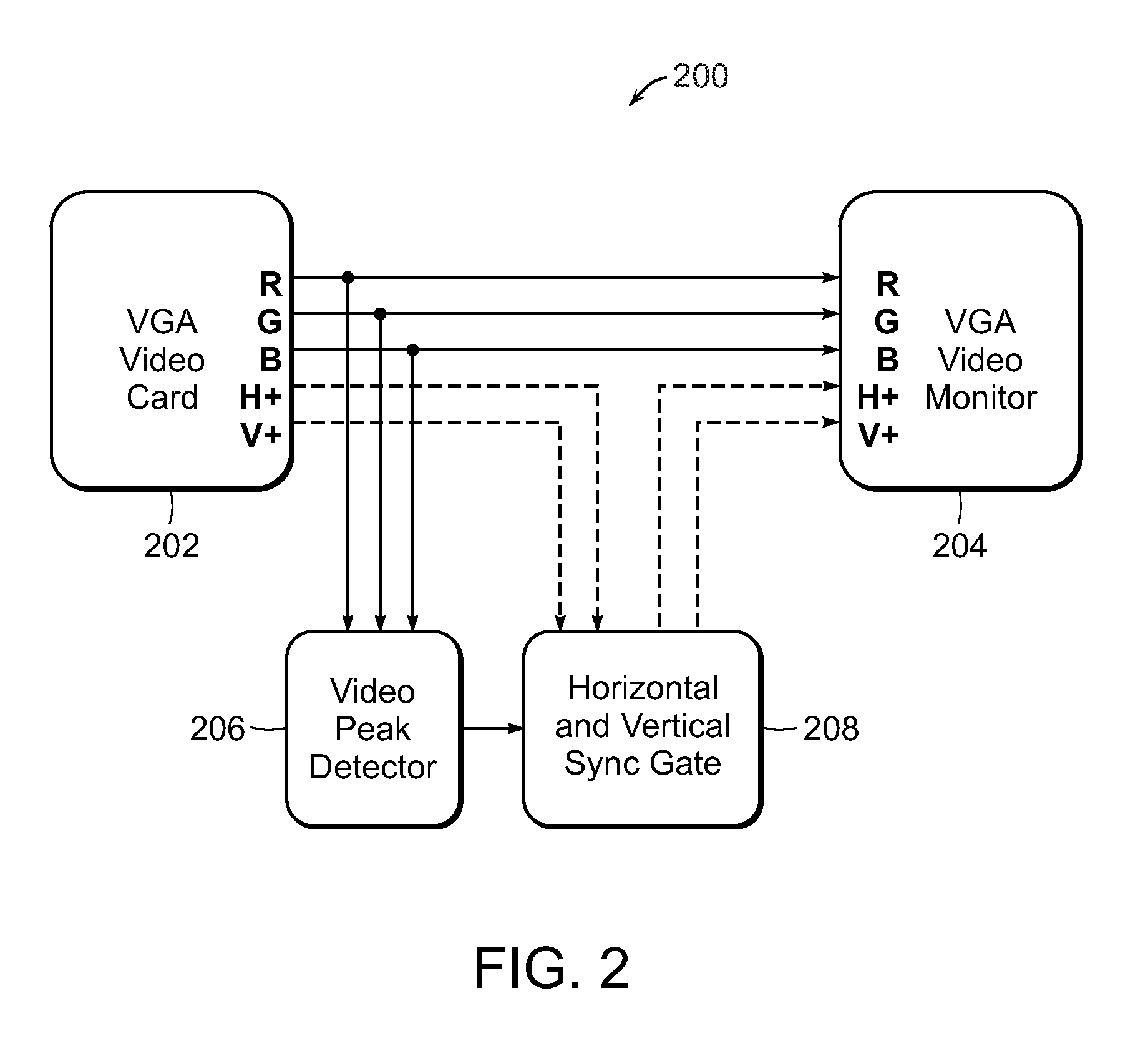
A CRT light pen emulating interface with power save and remote access for flat panel displays includes a pen flat panel display that indicates at least one of a user action with a light pen switch or other device and a presence of a light pen emulating object positioned on or proximate to a display surface of the electromagnetic pen flat panel display. A light pen emulating object is positioned proximate to the electromagnetic pen flat panel display. A processor generates a light pen emulation signal comprising position data for the light pen emulating object relative to the display surface of the electromagnetic flat panel display. A light pen CRT electronic interface converts the position data for the light pen emulating object into a corresponding signal that is comparable to a signal generated by a CRT light pen viewing a scanning dot on the CRT screen.

Description

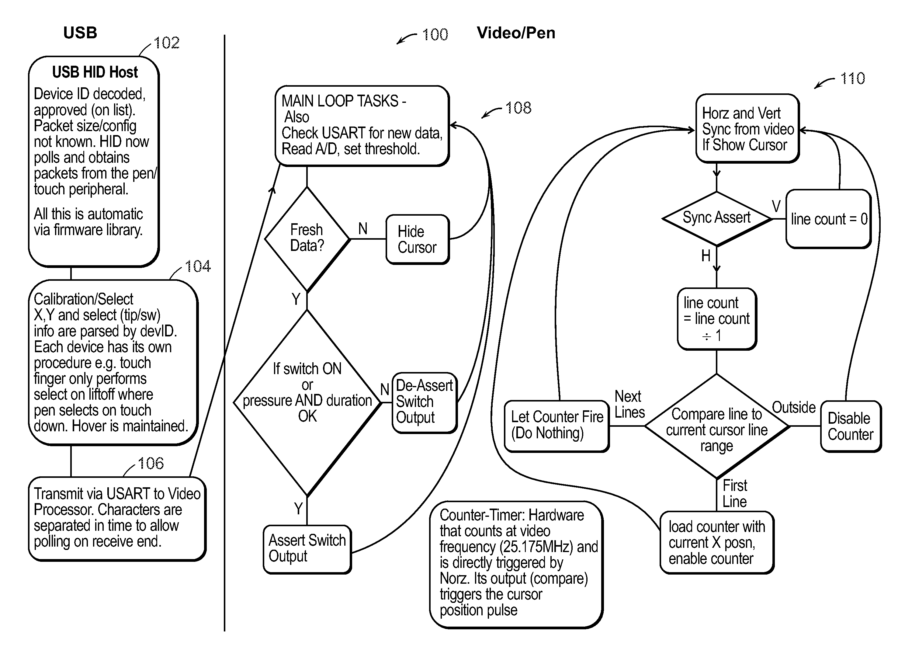
CROSS REFERENCE TO RELATED APPLICATIONS[0001]This patent application is a non-provisional of U.S. Provisional Patent Application Ser. No. 61 / 524,174 filed Aug. 16, 2011, entitled “CRT Light Pen Interface for Flat Panel Displays.” This patent application is also a non-provisional of U.S. Provisional Patent Application Ser. No. 61 / 612,653, filed Mar. 19, 2012, entitled “Light Pen Monitor Interface Power Saver Circuit.” This patent application is also a non-provisional of U.S. Provisional Patent Application Ser. No. 61 / 664,320 filed May 8, 2012, entitled “CRT Light Pen Interface for Flat Panel Displays with Remote Access.” The entire disclosures of these provisional patent applications are incorporated herein by reference.[0002]The section headings used herein are for organizational purposes only and should not to be construed as limiting the subject matter described in the present application in any way.INTRODUCTION[0003]Light pens have been used for many years with cathode-ray-tube (...

Claims


Application Information

Patent Timeline
IPC IPC(8): G06F3/033
CPCG06F1/325G06F3/0386Y02B60/32G06F3/03542G06F3/0416G06F3/04162Y02D30/50G06F3/037
Inventor BASNETT, ROBERT JOSEPHGREGORY, MITCHELL ALLENCOWELL, STEPHEN LEE
Owner PLASMABILITY
Learn More