Brake system for a vehicle and method for operating a brake system of a vehicle

Inactive Publication Date: 2013-02-28
ROBERT BOSCH GMBH
View PDF5 Cites 9 Cited by
  • Summary
  • Abstract
  • Description
  • Claims
  • Application Information

AI Technical Summary

Benefits of technology

[0030]Furthermore, the first pump, the second pump and/or the third pump may be situated on a common shaft of a motor. This reduces the required number of motors.
[0031]The brake system may in particular have exactly twelve controllable valves, which are controllable at least into an open state and into a closed state via an electrical signal provided by a control device of the brake system. The limitation of the valves required by the brake system, which are electrically switchable at least into the open state and into the closed state, to the number of twelve reduces the requirements and/or the costs for an electronics suited as a control device.
[0032]In another advantageous specific embodiment, the control device of the brake system may be configured to receive a power brake specification provided by a vehicle component, and, after receiving the power brake specification, control the block valve into an at least partially open state and to control the f

Problems solved by technology

However, operating the electric motor, for example the electric drive motor, in generator mode typically requires a certain minimum speed of the vehicle.
A recuperative brake system is thus frequently unable to exert a regenerative b

Method used


Image

  • Brake system for a vehicle and method for operating a brake system of a vehicle
  • Brake system for a vehicle and method for operating a brake system of a vehicle
  • Brake system for a vehicle and method for operating a brake system of a vehicle

Examples


Embodiment Construction

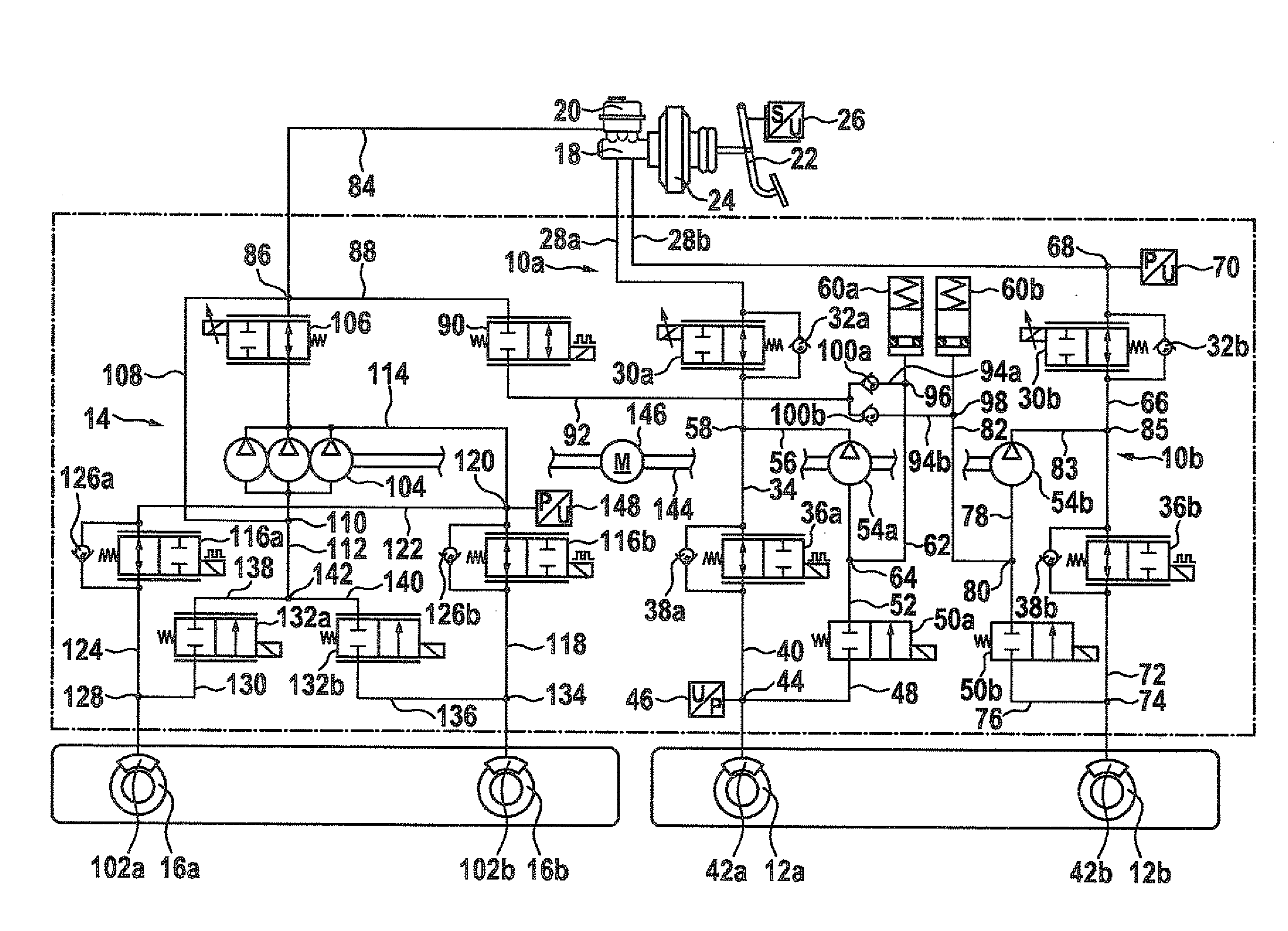
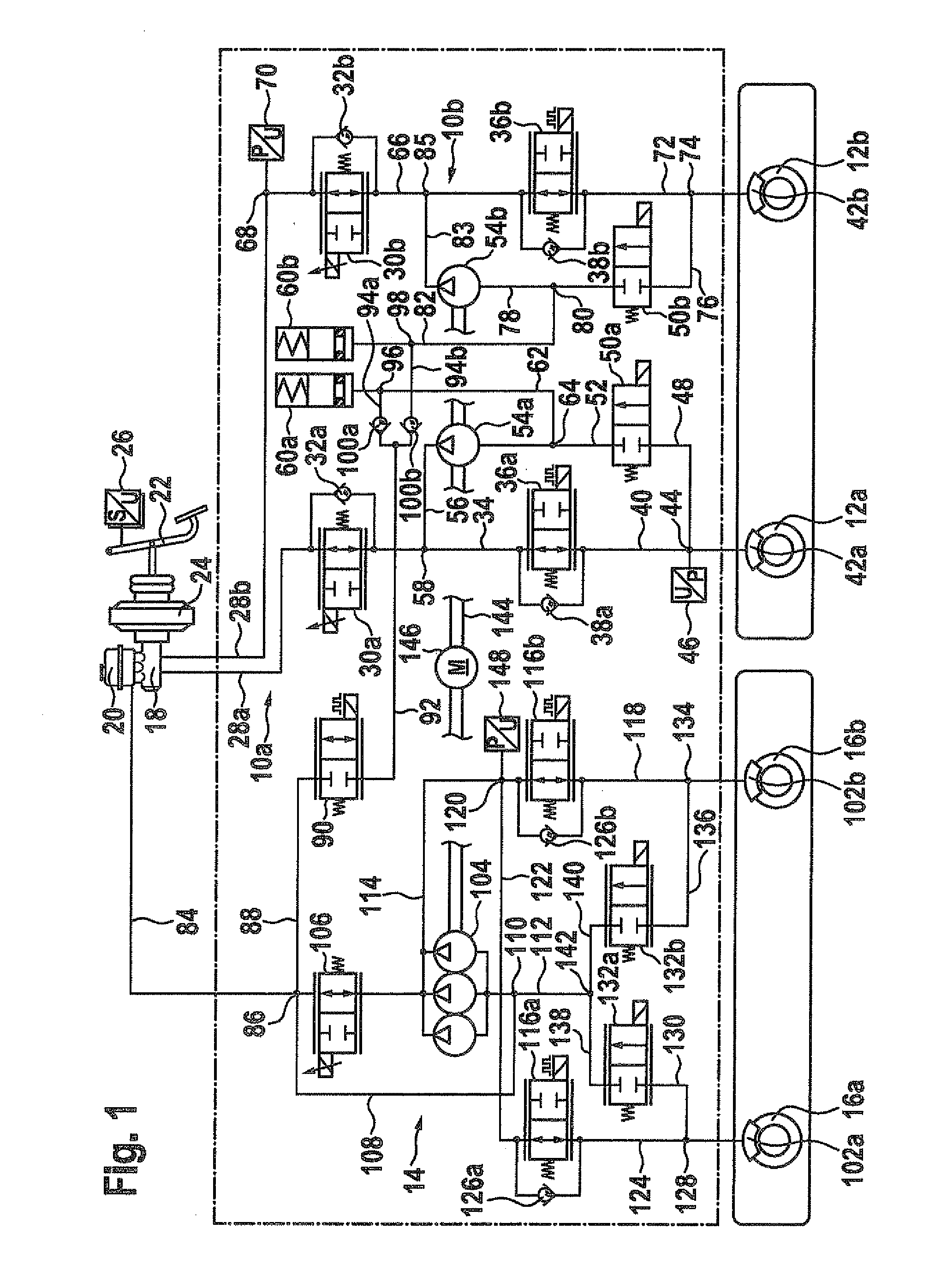
[0038]FIG. 1 shows a circuit diagram of a specific embodiment of the brake system. The brake system shown schematically in FIG. 1 is usable not only in an electric or hybrid vehicle. Instead, the brake system may also be used in a vehicle, for example, to ensure a preferred brake force distribution on the wheels of the vehicle when braking during cornering and / or driving in reverse. The indications, described below, of the use of the brake system in an electric or hybrid vehicle are to be understood merely by way of example.

[0039]The brake system comprises a first brake circuit 10a for braking a first wheel 12a, a second brake circuit 12b for braking a second wheel 12b and a third brake circuit 14 for braking a third wheel 16a and a fourth wheel 16b. Equipping the brake system with third brake circuit 14 is optional, however. First wheel 12a and second wheel 12b may be situated on a common axle of a vehicle, for example on the rear axle. The applicability of the brake system, howeve...


PUM


Abstract

A brake system and a method for operating same for a vehicle having a first wheel brake cylinder, into which a first brake medium volume is displaceable from a master brake cylinder, a second wheel brake cylinder, into which a second brake medium volume is displaceable from the master brake cylinder, a first pump associated with the first wheel brake cylinder and a second pump associated with the second wheel brake cylinder, the brake system including a block valve coupled to the brake medium reservoir, the first pump being able to pump a third brake medium volume through the at least partially open block valve and a first non-return valve into the first wheel brake cylinder, and the second pump being able to pump a fourth brake medium volume through an at least partially open block valve and the second non-return valve into the second wheel brake cylinder.

Description

FIELD OF THE INVENTION[0001]The present invention relates to a brake system for a vehicle. Furthermore, the present invention relates to a method for operating a brake system of a vehicle.BACKGROUND INFORMATION[0002]Electric and hybrid vehicles have a brake system configured for recuperative braking including an electric motor operated as a generator during recuperative braking. Following an intermediate storage, the electrical energy recovered during recuperative braking may be used for accelerating the vehicle. This makes it possible to reduce power loss, which a conventional vehicle incurs when braking frequently in travel, energy consumption and pollutant emission of the electric or hybrid vehicle.[0003]However, operating the electric motor, for example the electric drive motor, in generator mode typically requires a certain minimum speed of the vehicle. A recuperative brake system is thus frequently unable to exert a regenerative braking torque on the wheels of the vehicle for ...

Claims


Application Information

Patent Timeline
IPC IPC(8): B60T13/68B60T13/58
CPCB60T8/267B60T8/4872B60T8/348B60T8/26B60T8/3655B60T8/4054B60T8/4072B60T8/4275B60T8/48B60T13/58B60T13/686B60T2270/403
Inventor KUNZ, MICHAELSTRENGERT, STEFAN
Owner ROBERT BOSCH GMBH
Why Eureka
Try Eureka