Detection, Monitoring, and Management of Gas Presence, Gas Flow and Gas Leaks in Composites Manufacturing

a composites manufacturing and gas flow technology, applied in the direction of fluid tightness measurement, structural/machine measurement, instruments, etc., can solve the problems of voids and porosities in composites, leaks are a particularly common source of quality problems, and considerable time and effort is expended in managing and controlling vacuum pulled on parts, etc., to speed up the process of leak detection and repair, reduce the ambiguity and cost of leak check data

Active Publication Date: 2014-03-06
CONVERGENT MFG TECH
View PDF9 Cites 26 Cited by
  • Summary
  • Abstract
  • Description
  • Claims
  • Application Information

AI Technical Summary

Benefits of technology

[0017]In the present invention, one or more in-situ thermal mass flow sensors are provided. Each may be packaged with one or more other sensors into a ‘sensor package’, to monitor gas flow in composite manufacturing processes, including but not limited to autoclave and oven manufacturing of pre-impregnated material structures made of both thermoset and thermoplastic materials; and resin infusion or resin transfer moulding processes. For example, multiple sensor packages may be used to sense flow rates at multiple locations, such as within the breather, vacuum ports, vacuum hoses, and bladder vents. In one embodiment the invention reduces the ambiguity and cost of leak c

Problems solved by technology

A common defect in composites is the presence of voids and porosity.
It is generally accepted that a sufficient vacuum must be pulled on a part to achieve good quality, and considerable time and effort is expended in managing and controlling the vacuum pulled on a part.
Leaks are a particularly common source of quality problems.
Sources of leaks include but are not limited to improper sealing of seams between mould segments, improper sealing of flexible vacuum bags over the part and mould, puncturing of the flexible vacuum bag, failure of rubber and other hollow inserts, and failure of the solid mould or semi-flexible caul plate.
This procedure is time-consuming, particularly if a leak is found to be present, and the procedure must be repeated after every attempt to fix the leak.
Consequently the conventional leak detection method may take many hours to locate a single leak, causing significant and costly manufacturing downtime.
Furthermore, the procedure is sensitive to the size of the part, and the larger the part, the less sensitive the procedure.
Additionally, particularly in a very large part, there is currently no simple way to identify even the approximate location of the leak, other than by compartmentalizing the part.
A fundamental problem to date has been that the relationship between gas pressure and gas flow rates is complex.
Advani et al. describe that during the VARTM Process that checking the vacuum level is standard procedure especially when a large part is being made, as any air leakage will decrease the part quality.
Advani et al. further disclose that the primary leak isolation method which is conventionally used is performed by vacuuming the air out of the mould and if the vacuum pressure level has not decreased after a predetermined amount of time that the mould is considered to be free of air leaks,

Method used


Image

  • Detection, Monitoring, and Management of Gas Presence, Gas Flow and Gas Leaks in Composites Manufacturing
  • Detection, Monitoring, and Management of Gas Presence, Gas Flow and Gas Leaks in Composites Manufacturing
  • Detection, Monitoring, and Management of Gas Presence, Gas Flow and Gas Leaks in Composites Manufacturing

Examples


Embodiment Construction

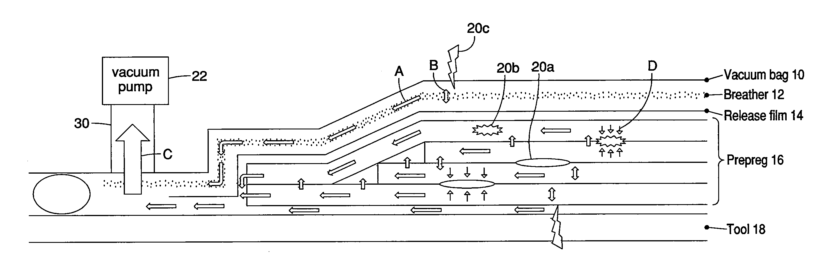
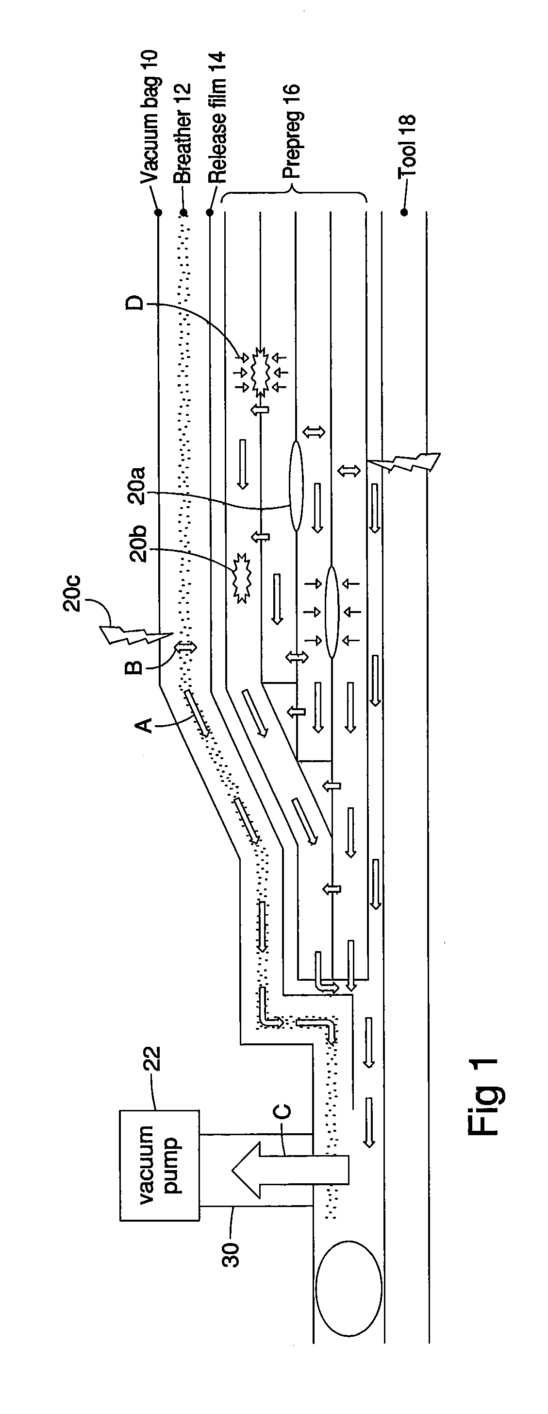
[0093]A schematic representation of void generation and dissipation is shown in FIG. 1. A vacuum bag or member 10 overlays a breather layer 12, which overlaps a release film 14. Release film 14 overlaps layers of pre-preg 16 which have been laid-up on tool or mould 18. As used herein, the term pre-preg refers to pre-impregnated composite fibres where a pre-cured or partially cured matrix bonding material, such as epoxy, is already present. These usually take the form of a weave or are uni-directional. Gas filled voids may be formed within pre-preg 16, caused by for example entrapped air 20a, volatiles or off-gasing 20b, or leaks 20c in bag 10, tool or mould 18, etc. Gas transport may be co-planar within or interleaved between the various layers as shown by arrows A, or may be orthogonal to the layers as shown by arrows B. Collectively the gas migrates to the vacuum source, indicated in FIG. 1 by arrow C leading to vacuum pump 22. Arrows D indicate void shrinkage or collapse.

[0094]FI...


PUM

PropertyMeasurementUnit
Temperatureaaaaaaaaaa
Pressureaaaaaaaaaa
Poweraaaaaaaaaa

Abstract

Porosity causing gas-based defects are detected, located, identified, and/or characterized by the use of defect information generated from gas flow data corresponding to gas flow characteristics measured by one or more sensors on a composite part processing piece such as a mould or membrane used during a composite manufacturing process. The defect information is generated using techniques including one or more of profiling the gas flow data, fingerprinting, line leak detection, analytical triangulation.

Description

CROSS REFERENCE TO RELATED APPLICATION[0001]This application claims priority from U.S. Provisional Patent Application No. 61 / 661,467 filed Jun. 19, 2012, entitled Detection, Monitoring, and Management of Gas Presence, Gas Flow and Gas Leaks in Composites Manufacturing.FIELD OF THE INVENTION[0002]This disclosure generally relates to methods for collecting and interpreting industrial process data, and more specifically to a system and method using in situ sensors to collect data during composite manufacturing, including preparatory bagging and sealing, as well as the processing inside an autoclave, oven, press or other composite manufacturing system.BACKGROUND OF THE INVENTION[0003]In composites manufacturing, the object is to produce the highest quality part possible. A common defect in composites is the presence of voids and porosity. Voids and porosity can be minimized by minimizing the sources of gas leading to such voids and porosity, and maximizing the removal and reduction of g...

Claims


Application Information

Patent Timeline
IPC IPC(8): B29C65/00G01M3/04
CPCG01M3/04B29C66/90B29C70/44B29C70/54
Inventor LANE, MALCOLM DAVIDPOURSARTIP, ANOSHIRAVANFERNLUND, GORANFLOYD, ANTHONY MICHAELVAN EE, DAVID ANDREWHIBBERT, MORGAN EDWIN JOHN
Owner CONVERGENT MFG TECH
Why Eureka
Try Eureka