Earth model estimation through an acoustic full waveform inversion of seismic data

a full waveform inversion and earth model technology, applied in the field of earth model estimation through acoustic full waveform inversion of seismic data, can solve the problems of depth/velocity ambiguity, local minima, and ambiguity between depth (z) and vertical acoustic velocity

Inactive Publication Date: 2013-11-21
SHELL OIL CO
View PDF10 Cites 56 Cited by
  • Summary
  • Abstract
  • Description
  • Claims
  • Application Information

AI Technical Summary

Benefits of technology

[0071]The method according to the present invention differs from the methods disclosed in the prior art references because it formulates full waveform inversion in a pseudo-time coordinate system. Therefore the vertical time of the reflected events are better preserved. The formulation of the earth model in a pseudo-time coordinate system instead of the depth coordinate system will help:

Problems solved by technology

Nevertheless, Full Waveform Inversion (FWI) suffers from the depth / velocity ambiguity because the model parameters are naturally represented in the spatial depth coordinate system.
One of the main difficulties with full waveform inversion (FWI) is the presence of local minima.
However, there is an ambiguity between depth (z) and vertical acoustic velocity.
From an inverse problem point of view, this means that the problem is ill posed.
Indeed, a modification of the earth model (m) above the hard contrasts can significantly change the time response of the reflected events and create a large phase error between the modelled and the observed data.
However, when the earth model is parameterized in the depth coordinate, it does not prevent the occurrence of phase mismatches between the late events, generally reflected events of the modelled and observed data.
However, this approach is also formulated in the depth coordinate system and therefore inherently suffers from the depth / velocity ambiguities.

Method used


Image

  • Earth model estimation through an acoustic full waveform inversion of seismic data
  • Earth model estimation through an acoustic full waveform inversion of seismic data
  • Earth model estimation through an acoustic full waveform inversion of seismic data

Examples


example 1

III) Example 1

[0119]To evaluate whether this approach is valid with large lateral variations, seismograms with different laterally-varying velocity models were computed and compared.

[0120]We first considered the velocity model in the pseudo-time coordinate system, FIG. 9.a, transformed it in the depth coordinate system, FIG. 9.b, and computed a reference shot gather.

[0121]Secondly, we perturbed by 20% the second layer of the velocity model FIG. 9.a, from 2000 m / s to 2400 m / s. Here, the perturbation is done in the pseudo-time model space. The velocity is displayed FIG. 10.a and FIG. 10.b after transformation in the depth coordinate system. The shot gather computed in this perturbed velocity model is plotted in black and white in the background of FIG. 11 while the reference shot gather is plotted in black wiggles. The two reflected events at about 2.8 s are in phase at short offsets, although the velocity difference in the second layer is 400 m / s. The reflected events approximately s...

example 2

IV) Example 2

[0126]Example 2 provides a simple full waveform inversion synthetic example.

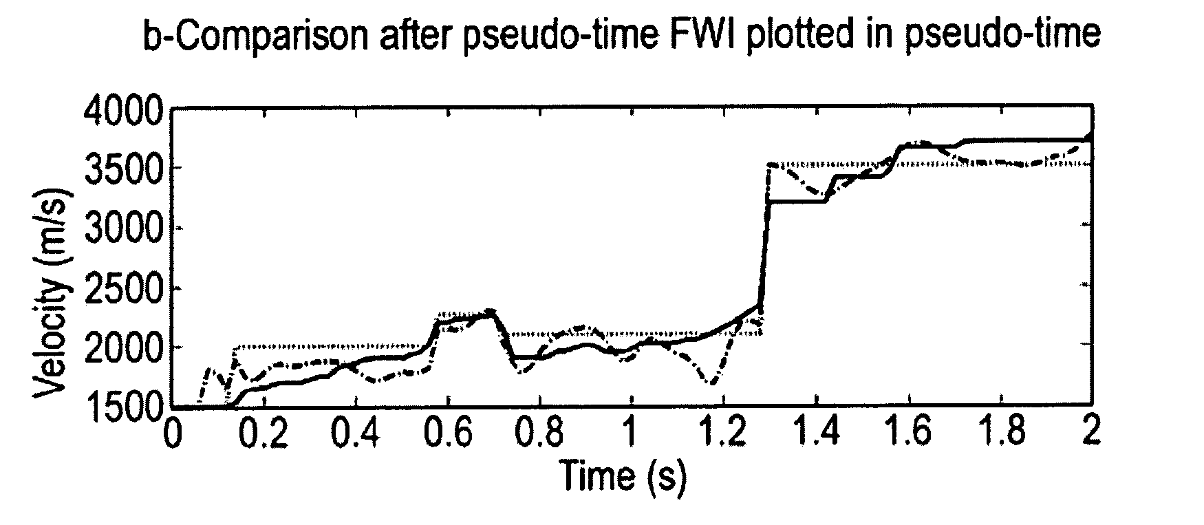
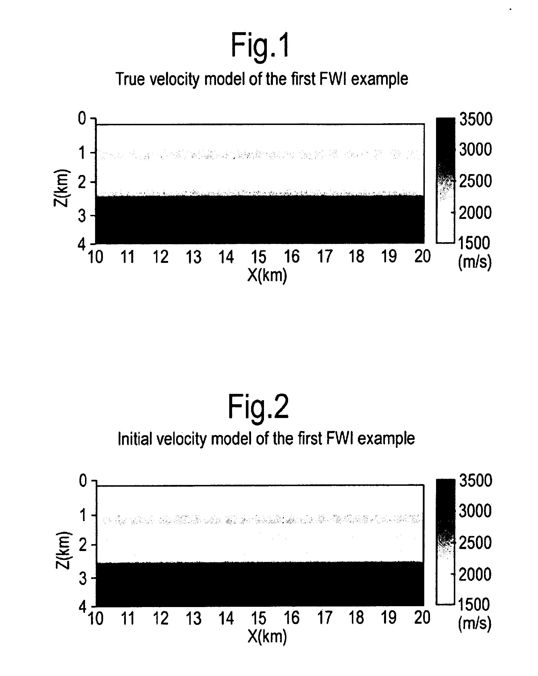
[0127]In Example 1 strong discontinuities were present in the initial model. Since we work at low frequencies, we may smooth these discontinuities before starting FWI. Here, we then present a simple FWI where the interfaces have been smoothed. The true velocity is displayed FIG. 19.a. The data are generated using the same acquisition geometry that in the first example. The initial velocity model is plotted FIG. 19.b. Using a multiscale approach, the frequencies 3, 4, 5, and 6.5 Hz are inverted. The FWI results are shown FIG. 20. Depth and pseudo-time FWI give similar results. The velocity inversion is however slightly better recovered with the pseudo-time formulation; see FIG. 22. To further evaluate the results, we picked the depths where the velocity becomes larger than 3500 m / s. This more or less corresponds to the horizon at about 2.7 km depth. The picked horizons in the four velocity models...


PUM


Abstract

An improved method of estimating an earth model utilizes an acoustic Full Waveform Inversion (FWI) of seismic data in a pseudo-time coordinate system, in which the earth model m({tilde over (m)}) is parameterized with two lateral coordinates (x,y) and a vertical coordinate ({tilde over (z)}) which expresses vertical travel time of acoustic signals used to generate the seismic data.

Description

BACKGROUND OF THE INVENTION[0001]The invention relates to a method for estimating an earth model using acoustic full waveform inversion of seismic data.[0002]Full Waveform Inversion (FWI) of seismic data helps improving the macro velocity model under acoustic vertical transversely isotropic assumption.[0003]Nevertheless, Full Waveform Inversion (FWI) suffers from the depth / velocity ambiguity because the model parameters are naturally represented in the spatial depth coordinate system.[0004]Full waveform inversion (FWI) automatically determines an earth model by minimizing the misfit between modelled and observed data. The minimization is solved with a local optimization technique with real-sized applications. This requires an initial guess.[0005]One of the main difficulties with full waveform inversion (FWI) is the presence of local minima. These local minima appear when the modelled data and the observed data are out of phase.[0006]Commonly, the earth model (m) is parameterized wit...

Claims


Application Information

Patent Timeline
Patent Type & Authority Applications(United States)
IPC IPC(8): G06F17/50
CPCG06F17/5009G01V1/30G06F30/20
Inventor PLESSIX, RENE-EDOUARD ANDRE MICHEL
Owner SHELL OIL CO
Why Eureka
Try Eureka