Multi-valve fluid operated cylinder positioning system

a fluid operated cylinder, multi-valve technology, applied in the direction of instrumentation, programme control, servomotors, etc., can solve the problems of inability to dynamically change the dynamic range of limit switch systems, wear, constant pressure, load, etc., to achieve accurate and inexpensive fluid operated cylinder positioning, maintain low cost and simplicity, and save costs.

Inactive Publication Date: 2008-04-08
PARKER INTANGIBLES LLC
View PDF66 Cites 27 Cited by
  • Summary
  • Abstract
  • Description
  • Claims
  • Application Information

AI Technical Summary

Benefits of technology

[0004]It would be desirable in the present invention to provide an inexpensive and accurate fluid operated cylinder positioning system. It would be desirable to provide a system relatively tolerant of pressure, load, and wear changes while maintaining low cost and simplicity. Accordingly, the present invention discloses an accurate and inexpensive fluid operated cylinder positioning system and method. Positioning a cylinder or valve mainstage based on differential pressure according to the present invention can be a viable method of control that is more cost effective and completely different from current offerings by industry leaders. The present invention uses standard, inexpensive components and techniques to achieve control with accuracy approaching that of an expensive system, but with a cost comparable to a simple system.
[0006]A multi-valve positioning system according to the present invention, by way of example and not limitation, such as a four-pack valve manifold, was developed primarily for pneumatic cylinder control. A cylinder has two active chambers that effect a change in position and force of the cylinder rod. The four-pack connects two proportional valves to each of these chambers, one to add fluid, such as air, to the chamber and one to remove fluid, such as air, from the chamber. The valves are manifolded to allow a reduction in packaging size and to reduce the required number of fluid connections from eight to four. The manifold also houses the control electronics and three pressure transducers. The electronics, along with onboard software, control the four valves in response to commands from an external source, i.e. a network or personal computer connection. The pressure transducers monitor inlet pressure and pressure on both sides of the cylinder in an effort to control the dispensing of fluid, such as air, to and from the cylinder, thereby allowing precise control of the rod output force. The present invention is believed to have one or more of the following novel aspects: (1) combining four electrically actuated, non-solenoid, direct acting proportional valves with control electronicsinto a single manifold for cylinder control; (2) integration of pressure transducers on the inlet to the manifold and both outlets; (3) use of pressure differential to determine position and force control of the cylinder rod; (4) integration of control electronics for position & force control directly in the valve pack; (5) operation of the valve pack using only the power from the control logic source, in this case a USB port of a notebook computer; and / or (6) reduction of size and weight of the valve pack while providing adequate performance to allow the valve pack to be integrated into the cylinder
[0007]It would be desirable in the present invention to provide very high performance levels for various pneumatic actuators without complex sensor / feedback systems. The present invention has primary applications with pneumatic cylinders, by way of example and not limitation, by using a “basic” cylinder equipped with “simple” position sensors, the present invention can provide the ability to accurately adjust the stop location of the cylinder piston at any point on the stroke, adjust acceleration / deceleration along the stroke and adjust velocity along the stroke, where all adjustments can be make “on the fly”, and the present invention can adjust and control the applied force by the cylinder, provide operating statistics of cylinder operation and diagnostic information for the controlled cylinder. The present invention can also be used in providing control of “large” process control valves. Various industries, for example petrochemical, water treatment, food and beverage processing, use valves with internal diameters greater than one inch (1″). Such valves are frequently operated in a proportional mode rather than simply on / off. Automated control of such valves is typically accomplished by a directly coupled electric motor or by operation of a pneumatically powered actuator. The present invention can improve control of such pneumatic actuators. The present invention can also control other pneumatic actuators or act as a positioner for a large valve. It can also be used to provide pressure regulation as an I / P or V / P transducer. Yet other applications exist that use pneumatic actuation, for example rotary motors. The present invention can be used to provide improved control of such devices.

Problems solved by technology

Although this type of system has significant cost advantages, it has some performance disadvantages.
Limit switch systems lack the ability to dynamically change the point or points at which the cylinder stops, and timing controlled systems require constant pressure, load, and wear.
Complex systems are more tolerant of pressure, load, and wear changes but have disadvantages in cost and complexity.
The complex systems typically use fragile or expensive sensor technology, and require a trained, experienced person for installation.

Method used


Image

  • Multi-valve fluid operated cylinder positioning system
  • Multi-valve fluid operated cylinder positioning system
  • Multi-valve fluid operated cylinder positioning system

Examples


Embodiment Construction

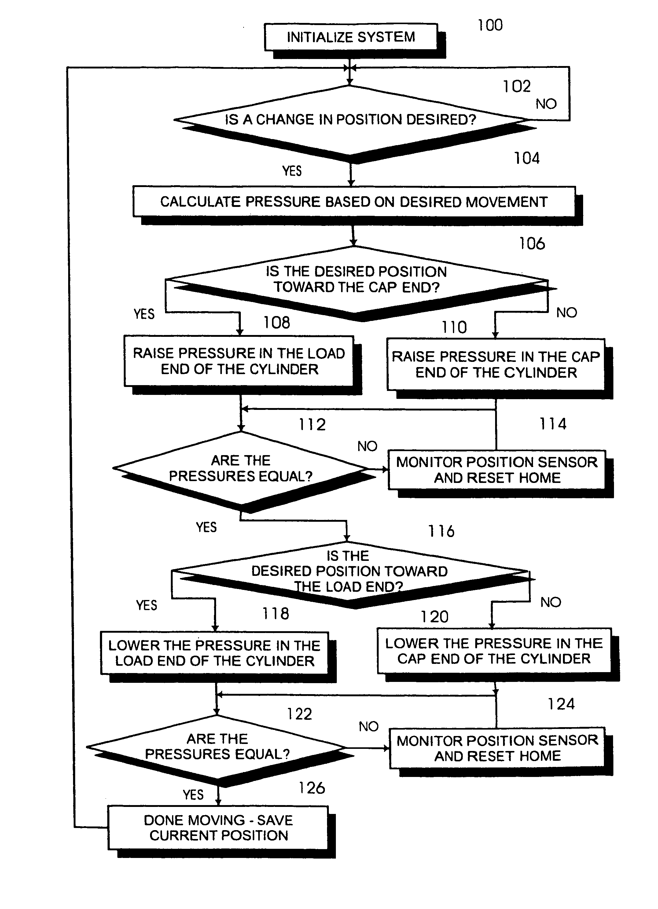
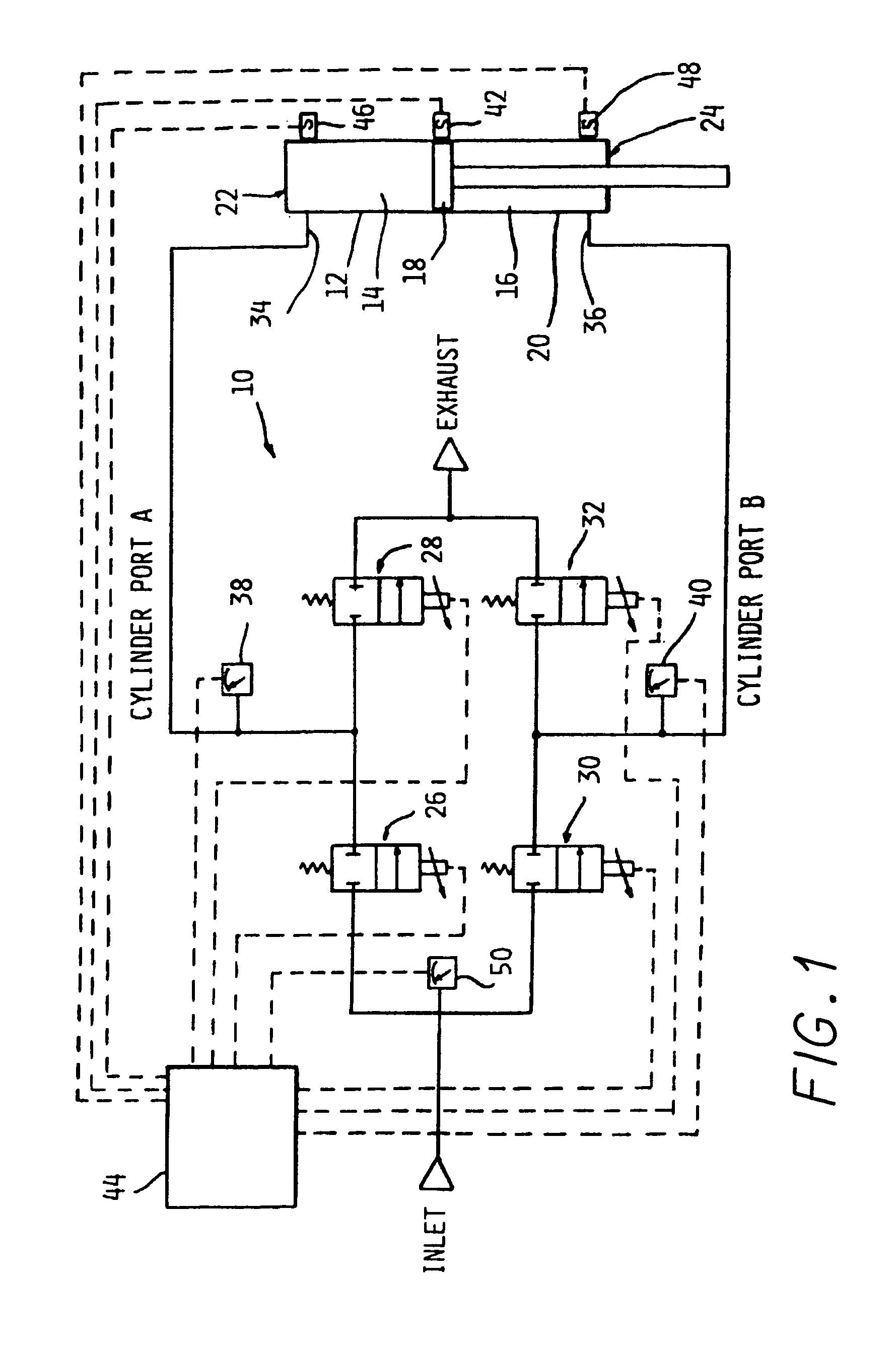
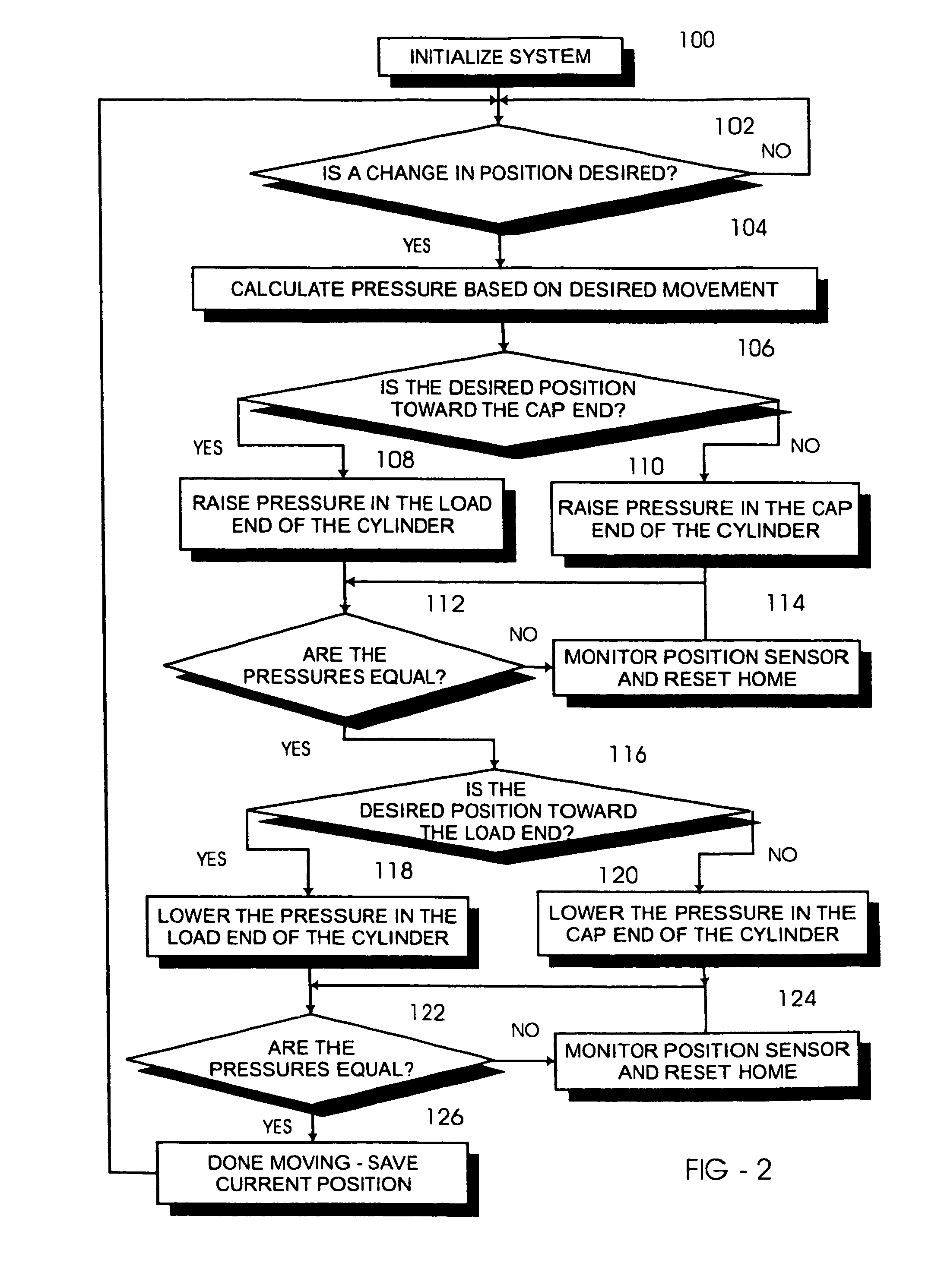
[0013]The present invention implements a pneumatic cylinder control scheme with a cost comparable to a simple system, but with performance approaching that of a complex system. The control scheme according to the present invention is a combination of hardware and software. The hardware is supportive of the required functions. However, actual operation is determined by the software. Further, the software is constructed in such a fashion that variables determine the actual final operation. This approach allows for example, a variety of motion profiles, i.e. control of acceleration / deceleration profiles, velocity, timing, force, repetition, etc. In addition, this control scheme allows operation of either dual acting cylinders or single acting cylinders. In other words, the present invention can operate cylinders with fluid control on both sides, or cylinders with fluid on one side and a mechanism such as a spring to cause return on the other side. Although the description contained her...


PUM


Abstract

A position control system is used for controlling a fluid operated cylinder having at least one fluid chamber defined by a piston located within a housing for movement between first and second end limits of travel. The system includes at least two electrically actuated proportional flow control valves connected to each port of the cylinder for selectively and proportionally controlling fluid flow into and out of the at least one chamber. At least one pressure sensor is provided for measuring fluid pressure with respect to each chamber. At least one discreet position sensor is located adjacent a midpoint of the cylinder for sensing a discreet centered position of the piston. A controller includes a program and is operably connected for controlling actuation of the at least two valves in response to pressure measured by the at least one pressure sensor and location measured by the at least one position sensor.

Description

CROSS-REFERENCE TO RELATED APPLICATIONS[0001]This application claims the benefit of provisional patent application Ser. No. 60 / 460,549 filed on Apr. 4, 2003, and is a continuation-in-part of application Ser. No. 10 / 763,500 filed Jan. 23, 2004, both of which are incorporated by reference herein in their entireties.FIELD OF THE INVENTION[0002]The present invention relates to a multi-valve positioning system for a fluid operated cylinder having at least one expandible chamber defined by a housing enclosing a movable piston.BACKGROUND OF THE INVENTION[0003]Sales of cylinder positioning systems have generally fallen into one of two categories, simple and complex. A simple system is inexpensive, and typically uses timing or limit switches to achieve control. Although this type of system has significant cost advantages, it has some performance disadvantages. Limit switch systems lack the ability to dynamically change the point or points at which the cylinder stops, and timing controlled sy...

Claims


Application Information

Patent Timeline
Patent Type & Authority Patents(United States)
IPC IPC(8): F15B15/28F15B9/09F15B11/00F15B11/048G05B19/43G05B19/44
CPCF15B9/09F15B11/006F15B11/048G05B19/43G05B19/44F15B2211/30575F15B2211/3111F15B2211/3144F15B2211/31576F15B2211/327F15B2211/6309F15B2211/6313F15B2211/6336F15B2211/6656F15B2211/7053F15B2211/7656G05B2219/41304G05B2219/41309G05B2219/41315G05B2219/41316
Inventor BUGEL, JOHNMOLER, JEFFOUDSHOORN, MARK P.
Owner PARKER INTANGIBLES LLC
Why Eureka
Try Eureka