Surface mounted pulse transformer

a pulse transformer and surface mount technology, applied in transformers/inductance details, transformers/inductance coils/windings/connections, electrical equipment, etc., can solve the problems of difficult positioning and soldering of coil ends, and achieve the effect of easy positioning of coil ends

Inactive Publication Date: 2013-02-28
HON HAI PRECISION IND CO LTD
View PDF5 Cites 40 Cited by
  • Summary
  • Abstract
  • Description
  • Claims
  • Application Information

AI Technical Summary

Benefits of technology

[0006]Accordingly, an object of the present invention is to provide

Problems solved by technology

The electrodes are disposed as plane pads, therefore the en

Method used


Image

  • Surface mounted pulse transformer
  • Surface mounted pulse transformer
  • Surface mounted pulse transformer

Examples


Embodiment Construction

[0015]Reference will now be made in detail to the preferred embodiment of the present invention.

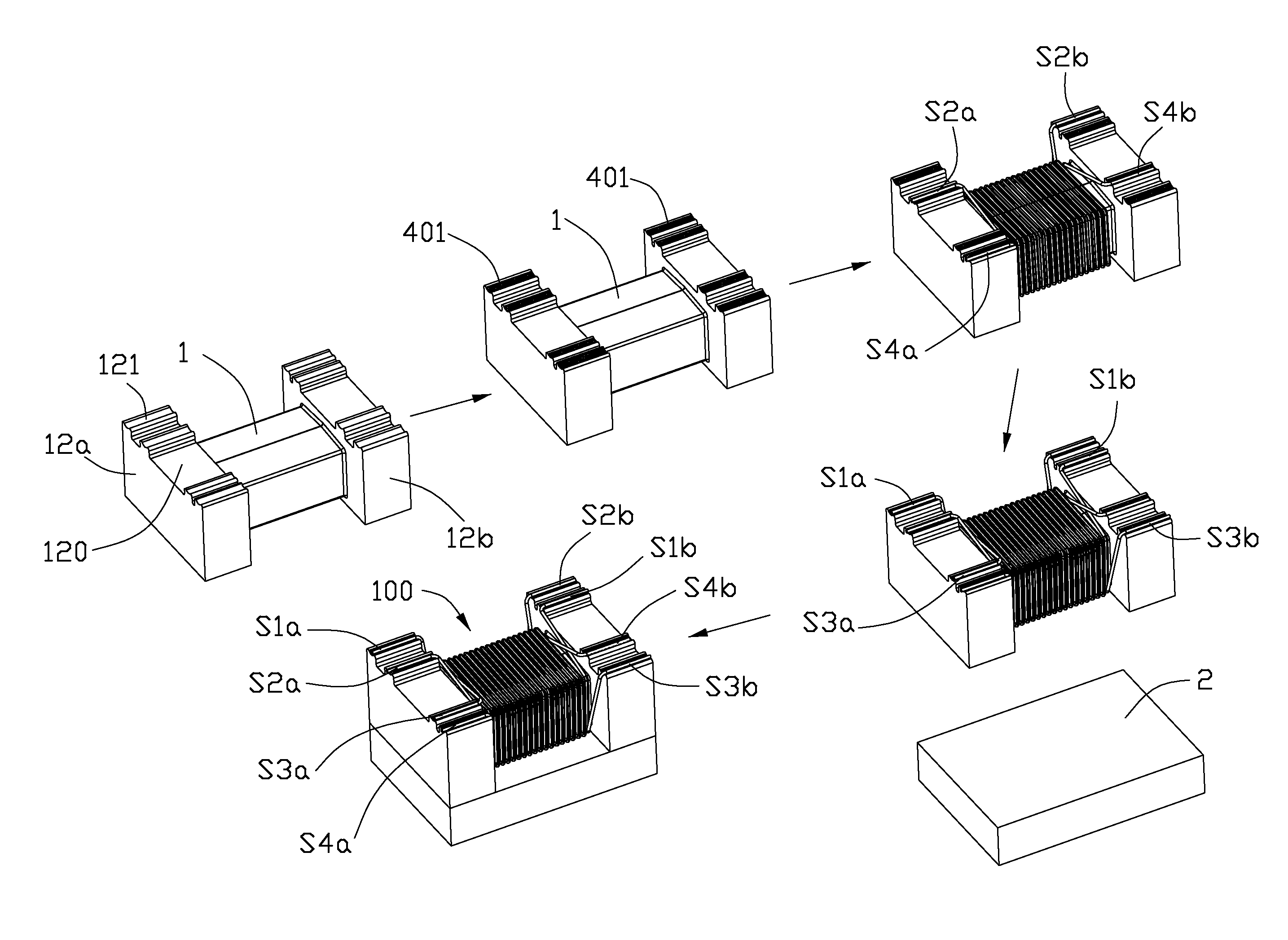
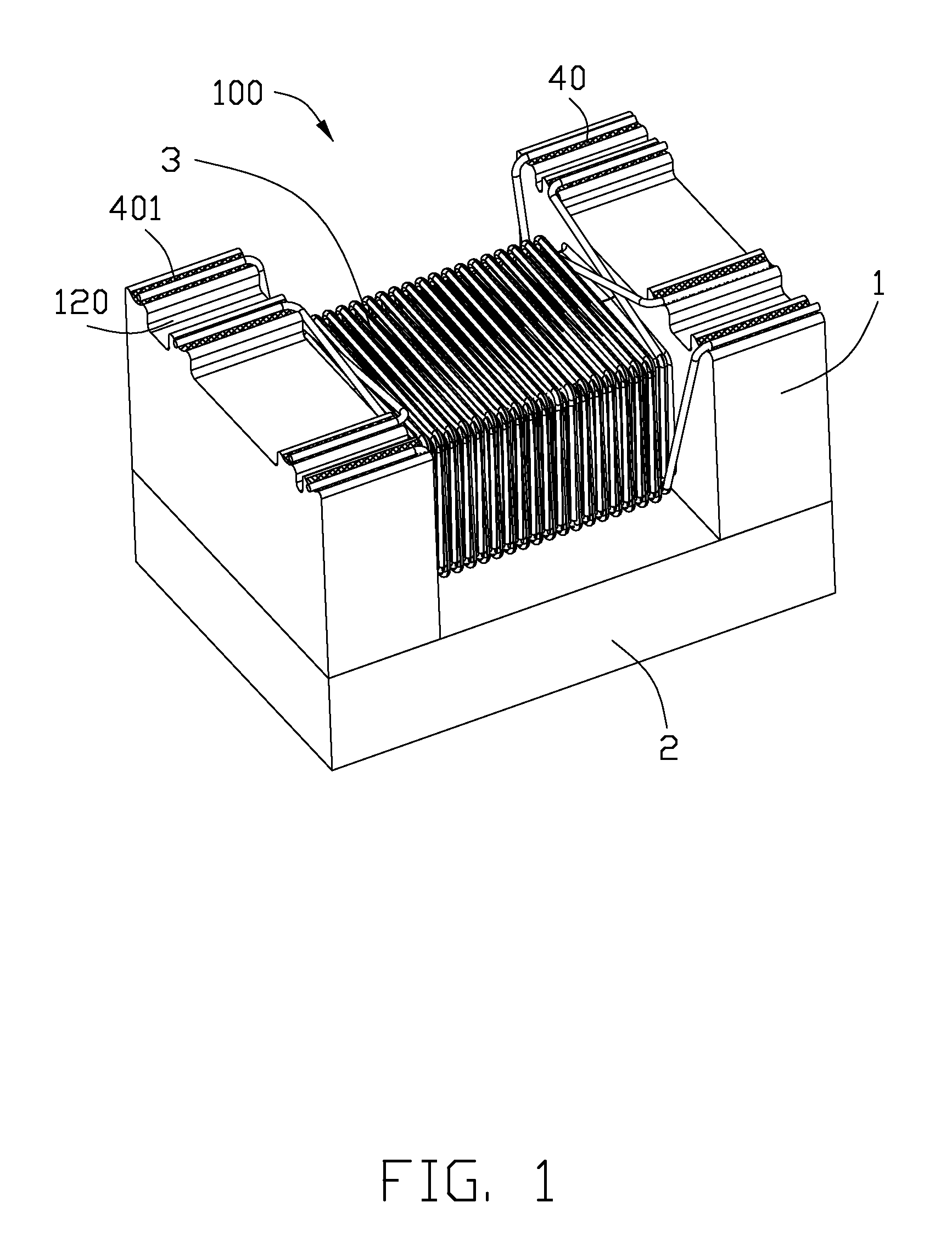
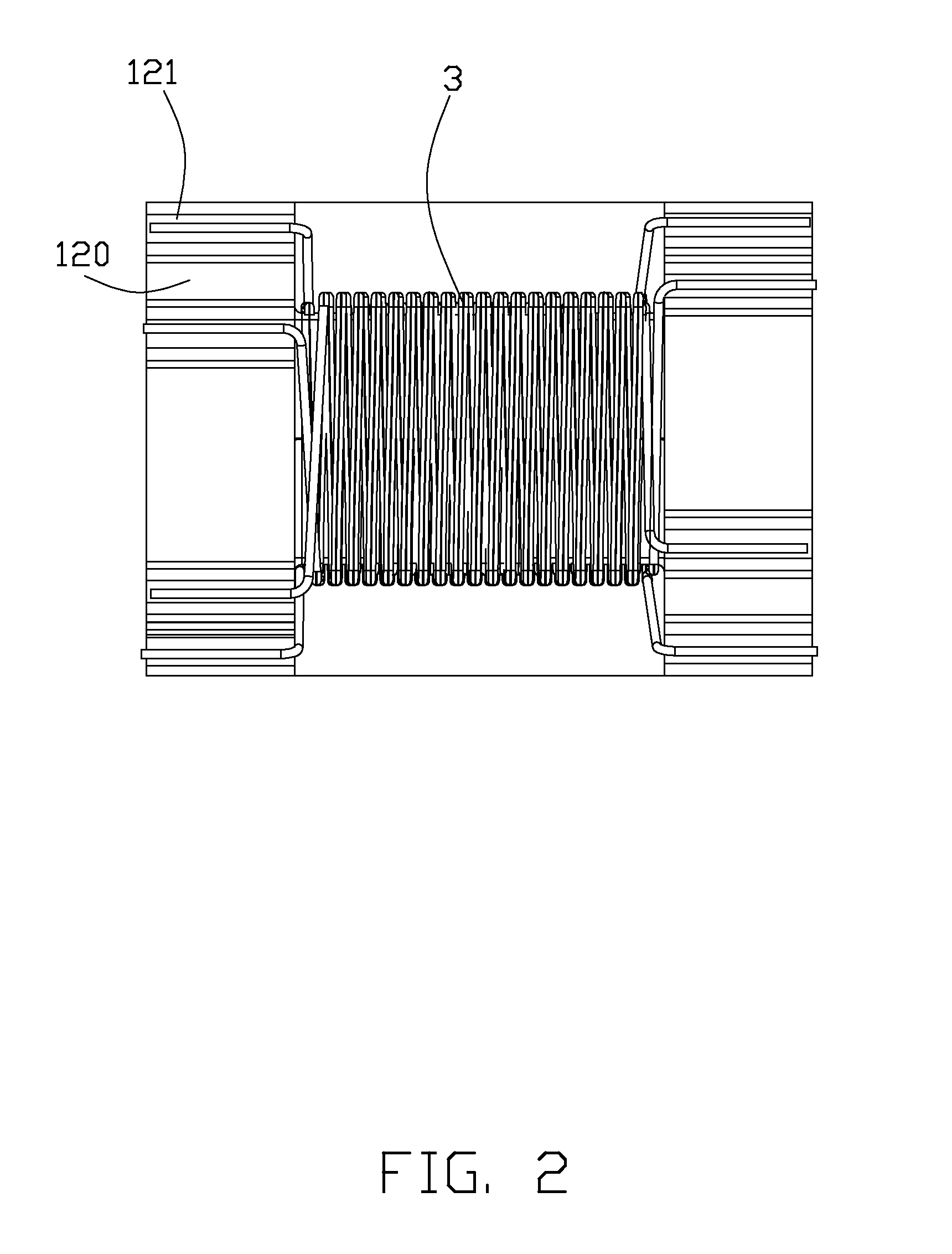
[0016]Referring to FIGS. 1-3, a surface mounted pulse transformer 100 according to a first embodiment of the present invention. The surface mounted pulse transformer 100 could be mounted to an external substrate. The surface mounted pulse transformer 100 includes a drum core 1, a lid 2 and a plurality of coils 3. The drum core 1 includes a core 11, a first flange 12a and a second flange 12b disposed on both ends of the core 11. The coils 3 wind around the core 11 to form a primary coil and a secondary coil (FIG. 5).

[0017]A plurality of electrodes 40 are formed on surfaces of the first and second flanges 12a, 12b and to be connected to the external substrate. The first flange 12a has four electrodes 40 each having an electrode groove 401 and three recesses 120 each disposed between two electrodes 40. A lower wall of each recess 120 protrudes outwardly from the core 11. The first flange 12a...


PUM


Abstract

A surface mounted pulse transformer (100) comprising a drum core (1) and a number of coils (3). The drum core includes a core (11), a first flange (12a) and a second flange (12b) disposed on both ends of the core. The number of coils wind around the core to form a primary coil and a secondary coil. A number of electrodes (40) are formed on surfaces of the first and second flanges and to be connected to an external substrate. The ends of the coils are physically and electrically connected to the electrodes. One of the electrodes has an electrode groove (401) for receiving and positioning one end of the coils.

Description

BACKGROUND OF THE INVENTION[0001]1. Field of the Invention[0002]The present invention relates to a surface mounted pulse transformer.[0003]2. Description of Related Art[0004]U.S. Pat. No. 8,093,980 discloses a surface mounted pulse transformer including a drum type core and a plurality of coils. The drum type core includes a core, a first flange and a second flange disposed on both ends of the core. The plurality of coils wind around the core to form a primary coil and a secondary coil. A plurality of electrodes are formed on surfaces of the first and second flanges and to be connected to an external substrate. The ends of the coils are physically and electrically connected to the electrodes. The electrodes are disposed as plane pads, therefore the ends of the coils are difficult to be positioned and soldered.[0005]U.S. Pat. No. 7,256,673 discloses a common-mode choke coil including a core, first and second conducting wires, and first and second electrode parts. The core includes a ...

Claims


Application Information

Patent Timeline
IPC IPC(8): H01F27/29
CPCH01F27/292
Inventor HUANG, LUN-TSUXU, CAI-GANGLU, ZHI
Owner HON HAI PRECISION IND CO LTD
Why Eureka
Try Eureka