Cable Carrier Device

a carrier device and cable technology, applied in the direction of instruments, manufacturing tools, optical elements, etc., can solve problems such as difficult installation

Inactive Publication Date: 2013-03-07
OPTERNA AM INC
View PDF10 Cites 16 Cited by
  • Summary
  • Abstract
  • Description
  • Claims
  • Application Information

AI Technical Summary

Benefits of technology

[0007]In one embodiment, a carrier device for advancing a fiber optic cable having a connector on one end of the fiber optic cable through a conduit includes a first carrier member defining a first hollow portion with a first width and a second hollow portion with a second width. The first hollow portion is configured to receive a first portion of a connector on one end of a fiber optic cable. The carrier device also includes a second carrier member configured to be selectively coupled to the first carrier member such that a connector seated in the first hollow portion is securely coupled to the carrier device. The second width is smaller than the first width.

Problems solved by technology

Consequently, connectors often snag on other fiber optic cables and objects within the conduit, making installation difficult.

Method used


Image

  • Cable Carrier Device
  • Cable Carrier Device
  • Cable Carrier Device

Examples


Embodiment Construction

[0015]In the detailed description that follows, references to “one embodiment,”“an embodiment,”“an example embodiment,” etc., indicate that the embodiment described may include a particular feature, structure, or characteristic, but every embodiment may not necessarily include the particular feature, structure, or characteristic. Moreover, such phrases are not necessarily referring to the same embodiment. Further, when a particular feature, structure, or characteristic is described in connection with an embodiment, it is submitted that it is within the knowledge of one skilled in the art to affect such feature, structure, or characteristic in connection with other embodiments whether or not explicitly described.

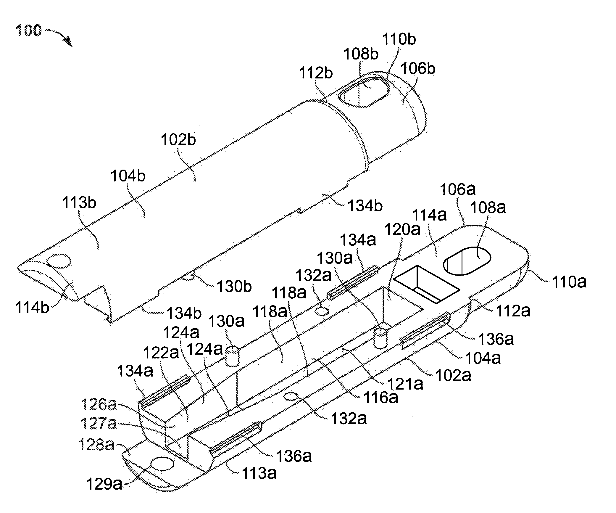
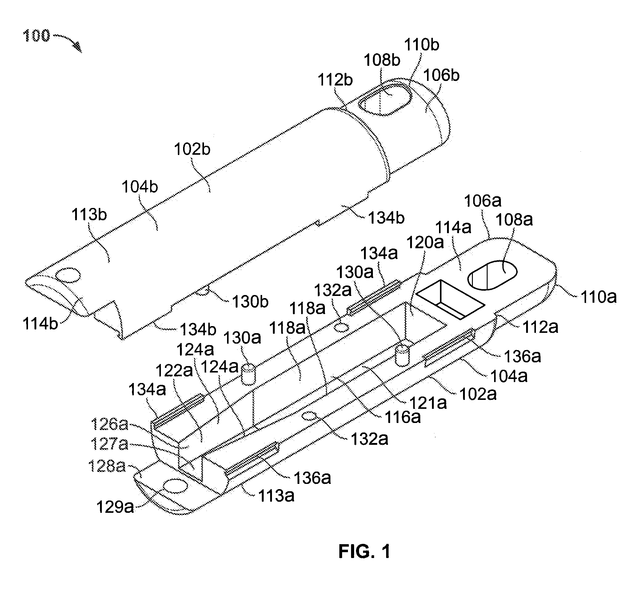
[0016]FIG. 1 is a perspective view of a carrier device 100. As shown in FIG. 1, carrier device 100 includes a first carrier member 102a and a second carrier member 102b. First carrier member 102a is selectively coupled to (i.e., joined with) second carrier member 102b to secu...


PUM

PropertyMeasurementUnit
widthaaaaaaaaaa
forceaaaaaaaaaa
diameteraaaaaaaaaa

Abstract

A carrier device for advancing a fiber optic cable having a connector on one end of the fiber optic cable through a conduit includes a first carrier member and a second carrier member configured to be selectively coupled to the first carrier member. The first carrier member defines a first hollow portion with a first width and a second hollow portion with a second width. The first hollow portion is configured to receive a first portion of a connector on one end of a fiber optic cable. A connector seated in the first hollow portion is securely coupled to the carrier device.

Description

BACKGROUND[0001]1. Field[0002]The present invention relates to a carrier device for use with a cable and, particularly, a carrier device for use with a fiber optic cable having a connector.[0003]2. Background Art[0004]Typically, during fiber optic cable installation, a fiber optic cable travels from one point to another. For example, in a multi-unit building installation, fiber optic cables may travel from a fiber optic collector plate on the first floor of a building to a fiber distribution terminal on a higher floor of the building. For protection and organization of fiber optic cables along such lines of travel, the fiber optic cables are generally run through a protective conduit.[0005]A fiber optic cable may include a connector at one end of the cable to optically couple the fibers of the fiber optic cable to another cable, device, or light source. Generally, during installation, a cord (e.g., a nylon string or cable) is advanced through a conduit, and attached to the connector...

Claims


Application Information

Patent Timeline
Patent Type & Authority Applications(United States)
IPC IPC(8): G02B6/46B23P11/00
CPCG02B6/4465Y10T29/49826G02B6/4466G02B6/545G02B6/475
Inventor MATHEW, AJILIVELIL THOMASPARAMESWARAN CHANDRAN, KIZHAKKEKUTTUARAKKAKUDY, BIJI MATHEWSANITH, SUDHAKARAN K.NAIR, K.R. SURESH
Owner OPTERNA AM INC
Why Eureka
Try Eureka