Card device and socket

Active Publication Date: 2013-03-07
PANASONIC INTELLECTUAL PROPERTY MANAGEMENT CO LTD
View PDF5 Cites 9 Cited by
  • Summary
  • Abstract
  • Description
  • Claims
  • Application Information

AI Technical Summary

Benefits of technology

The invention is about a card device that can send high-frequency signals, and a socket that can hold the card device.

Problems solved by technology

Even on the basis of the aforementioned improvements, the high frequency signal transmission between the conventional socket and the SD memory card with the two electrode arrays may not be optimized.

Method used


Image

  • Card device and socket
  • Card device and socket
  • Card device and socket

Examples


first embodiment

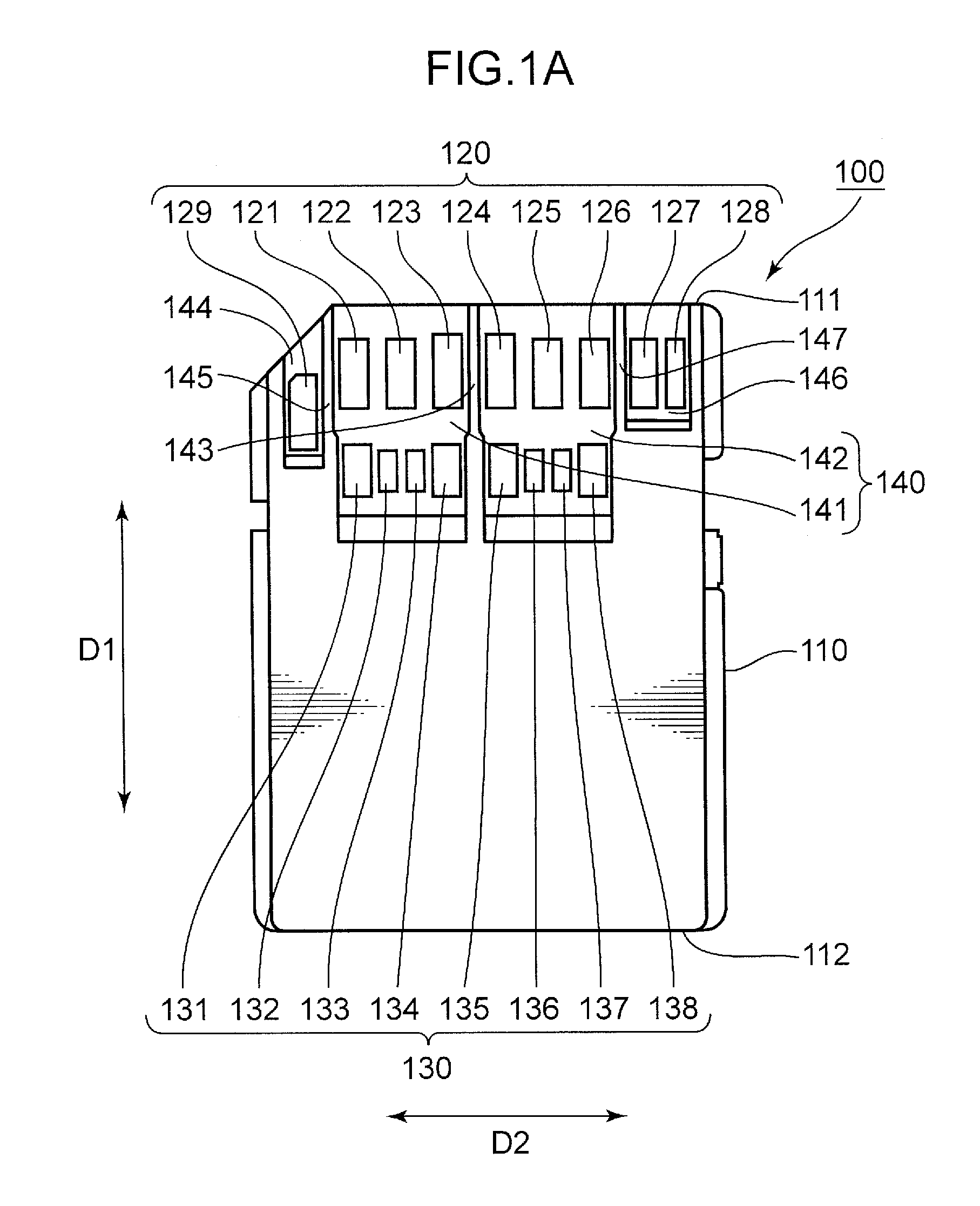
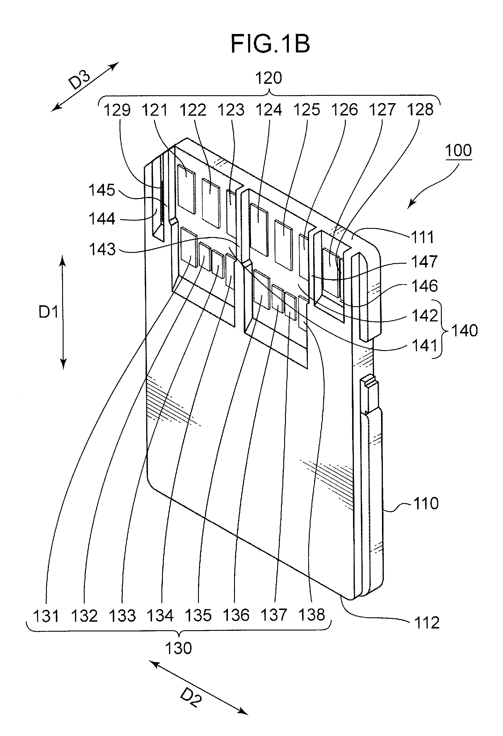
[0066]FIG. 1A is a schematic plan view of the SD memory card exemplified as the card device according to the first embodiment. FIG. 1B is a schematic top perspective view of the SD memory card shown in FIG. 1A. FIG. 1C is a schematic bottom perspective view of the SD memory card shown in FIG. 1A. The SD memory card is described with reference to FIGS. 1A to 1C and FIGS. 27A to 27C.

(SD Memory Card)

[0067]The SD memory card 100 shown in FIGS. 1A to 1C is inserted into and ejected from a host device (not shown) such as a personal computer in a first direction D1, like the conventional SD memory card 900 described with reference to FIGS. 27A to 27C. The SD memory card 100 includes a housing 110 which has a substantially rectangular box shape. The housing 110 includes a leading edge 111, which is inserted into the host device on ahead, and a trailing edge 112 opposite to the leading edge 111. In this embodiment, the housing 110 is exemplified as the first housing.

[0068]The SD memory card ...

second embodiment

[0117]FIGS. 6A to 6C show an SD memory card exemplified as the card device according to the second embodiment. The SD memory card of the second embodiment may appropriately overcome the aforementioned problems.

[0118]FIG. 6A is a schematic plan view of the SD memory card which is exemplified as the card device according to the second embodiment. FIG. 6B is a schematic top perspective view of the SD memory card shown in FIG. 6A. FIG. 6C is a schematic bottom perspective view of the SD memory card shown in FIG. 6A. The SD memory card of the second embodiment is described with reference to FIGS. 1A to 1C, FIGS. 6A to 6C and FIGS. 27A to 27C.

[0119]The SD memory card 100A of the second embodiment includes a housing 110A in addition to the first and second electrode arrays 120, 130 like the SD memory card 100 of the first embodiment. It should be noted that the arrangement pattern of the first electrodes 121 to 129 of the first electrode array 120 and the arrangement pattern of the second ...

third embodiment

[0130]FIG. 7 shows a socket configured to selectively receive and eject the SD memory card 100A described in the context of the second embodiment and the conventional SD memory card 900. The socket described in the context of the third embodiment uses the detection regions 162, 164 of the SD memory card 100A to identify a shape of the housings 110A, 910 of the SD memory cards 100A, 900. Consequently, the problem about the high contact pressure described in the context of the first embodiment may be appropriately overcome. In this embodiment, the housing 110A of the SD memory card 100A is exemplified as the first housing. The conventional SD memory card 900 is exemplified as another card device. The housing 910 of the SD memory card 900 is exemplified as the second housing. The socket is described with reference to FIGS. 6A, 7 and 27.

[0131]In addition to the first contact pin array 320, the second contact pin array 330 and the fixing member 340 like the socket 300 described in the co...


PUM


Abstract

The present application discloses a card device configured to be inserted into and ejected from a host device in a first direction. The card device includes a first housing including a leading edge which is inserted into the host device on ahead, and a trailing edge opposite to the leading edge; a first electrode array including first electrodes aligned in a second direction along the leading edge; and a second electrode array including second electrodes aligned in the second direction between the first electrode array and the trailing edge. The second electrodes include an electrode shifted from the first electrodes in the second direction.

Description

TECHNICAL FIELD[0001]The present invention relates to a card device suitable for high frequency signal transmission, and a socket into which the card device is inserted.BACKGROUND ART[0002]For example, a compact card device (e.g., a memory card), which uses a mass storage flash device formed from a semiconductor material, is broadly used in recent years not only in a field of information processing apparatuses which process digital information, but also in various industrial applications such as in-car equipment mounted in vehicles. In particular, an SD memory card is one of the most popular card devices.[0003]FIG. 27A is a schematic plan view of a conventional SD memory card. FIG. 27B is a schematic top perspective view of the conventional SD memory card. FIG. 27C is a schematic bottom perspective view of the conventional SD memory card. The conventional SD memory card is described with reference to FIGS. 27A to 27C.[0004]The conventional SD memory card 900, which is used as a remo...

Claims


Application Information

Patent Timeline
IPC IPC(8): H01R12/72
CPCG06K19/07743G06K19/07732
Inventor NAKAMURA, YUTAKA
Owner PANASONIC INTELLECTUAL PROPERTY MANAGEMENT CO LTD
Why Eureka
Try Eureka