Terminal-crimped cable

Inactive Publication Date: 2014-10-09
YAZAKI CORP
View PDF9 Cites 0 Cited by
  • Summary
  • Abstract
  • Description
  • Claims
  • Application Information

AI Technical Summary

Benefits of technology

The present invention provides a terminal-crimped cable that can reduce production cost by using a core made of a single conductive wire. However, this can cause an increase in contact resistance between the core and the crimp portion. To address this issue, the invention uses a specific crimp method that increases the contact pressure between the core and the crimp portion, reducing the likelihood of an increase in contact resistance. This creates a more reliable connection between the core and the crimp portion, ensuring the stability of the overall terminal-crimped cable.

Problems solved by technology

Incidentally, since the conventional terminal-crimped cable described above has such a structure that since the core is made of the plurality of conductive wires, the larger the cross section of the core is, the larger the number of used conductive wires are, thus increasing production cost.
However, when the crimp portion is to be crimped to the core, unlike the core made of the plurality of conductive wires, the core made of the single conductive wire does not move in the crimp portion, thus making it difficult to disperse a load applied to the core by crimping the crimp portion.
Accordingly, in the crimp portion of the terminal, an environmental change such as high temperature or low temperature caused a creep to a portion especially having a high contact pressure to thereby decrease contact pressure, failing to secure a sufficient contact pressure in the crimp portion, thus causing such a fear as that the contact resistance between the core and the crimp portion might be increased.

Method used


Image

  • Terminal-crimped cable
  • Terminal-crimped cable
  • Terminal-crimped cable

Examples


first embodiment

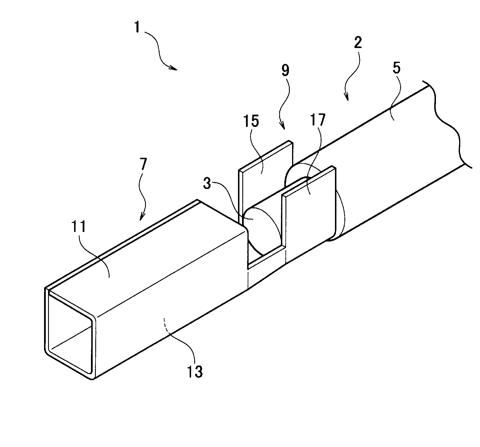
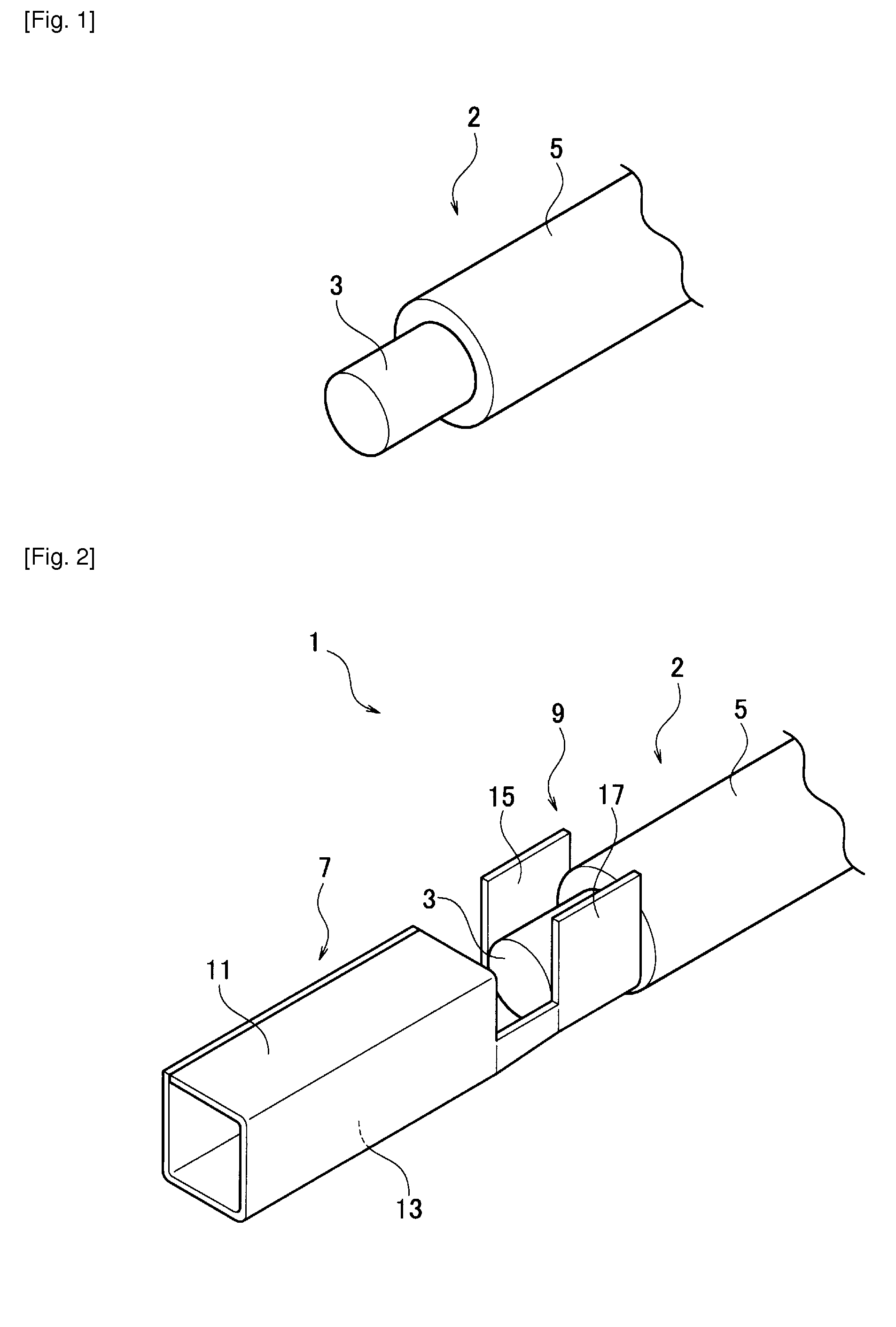
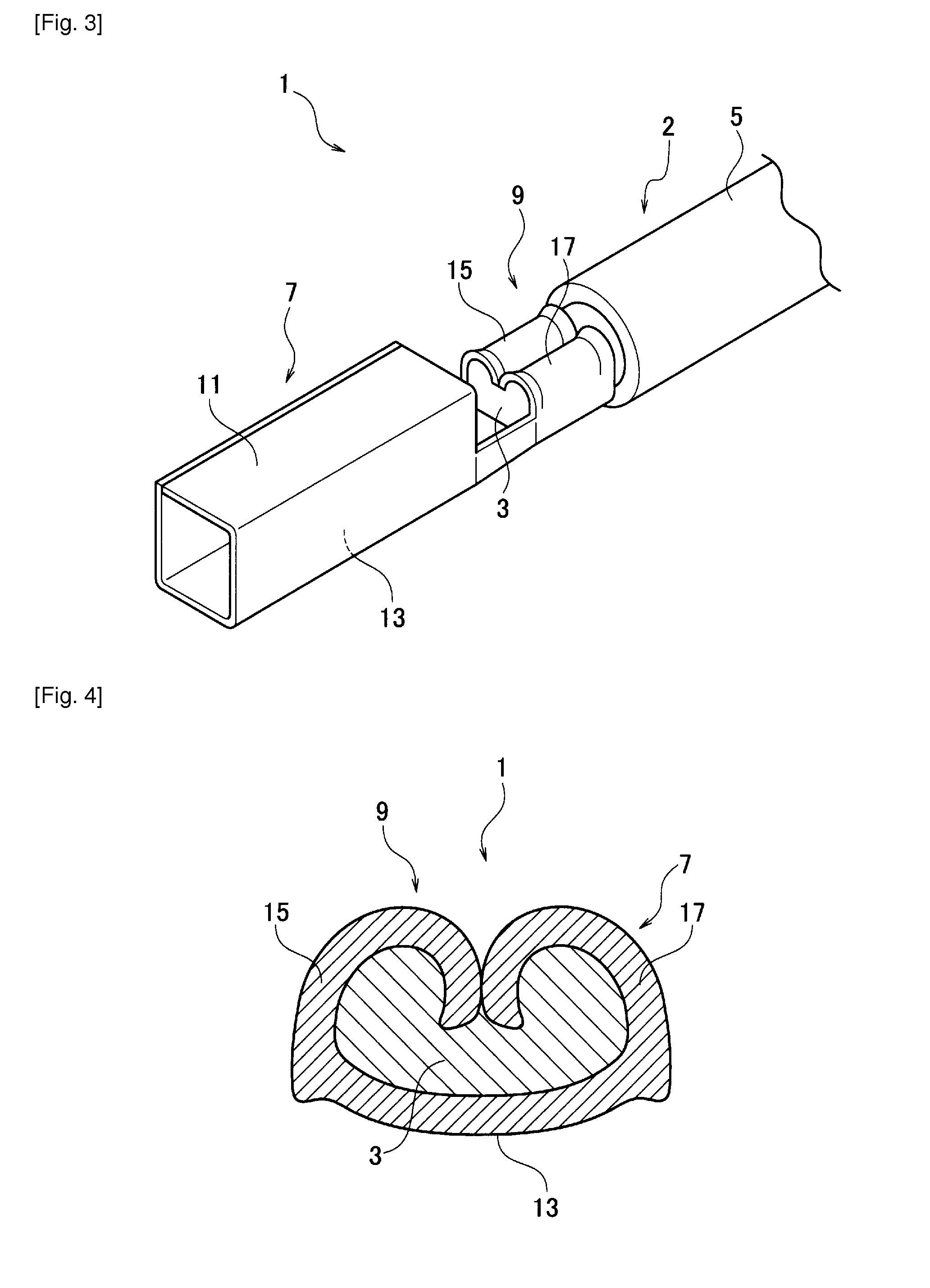
[0027]By using FIG. 1 to FIG. 4, a terminal-crimped cable 1 according to a first embodiment will be explained.

[0028]The terminal-crimped cable 1 according to the first embodiment includes: a cable 2 including a core 3 made of a single conductive wire and a jacket 5 for covering an outer periphery of the core 3 having an end portion exposed from the jacket; and a terminal 7 having a crimp portion 9. The crimp portion 9 of the terminal 7 is crimped to the end portion of the core 3 exposed from the jacket 5, so that the terminal 7 is made conductive with the core 3.

[0029]Then, in a state that the end portion of the core 3 exposed from the jacket 5 is heated and softened, the crimp portion 9 is crimped to the end portion of the core 3.

[0030]As illustrated in FIGS. 2 and 3, the terminal 7 made conductive with the cable 2 includes a contact portion 11 and the crimp portion 9. The contact portion 11 is made of a female receptacle. When a tab of a male terminal (not illustrated) as a mating...

second embodiment

[0041]By using FIG. 5, a terminal-crimped cable 101 according to a second embodiment will be explained.

[0042]In the terminal-crimped cable 101 according to the second embodiment, the jacket 5 on the core 3 side exposed from the jacket 5 of the cable 2 is also crimped to a crimp portion 105 of a terminal 103. Herein, according to the second embodiment, to similar structural elements as those according to the first embodiment will be added the same reference numerals or signs, and explanations of the structure and function will be omitted as reference can be made to those according to the first embodiment; however, since the terminal-crimped cable 101 according to the second embodiment has the same structure as that according to the first structure, the effect brought about by the second embodiment is similar as that brought about by the first embodiment.

[0043]As illustrated in FIG. 5, the crimp portion 105 of the terminal 103 has the bottom wall 13 extending from the core 3 to the ja...


PUM


Abstract

A terminal-crimped cable (1) includes: a cable (2) including a core (3) made of a single conductive wire and a jacket for covering an outer periphery of the core (3) having an end portion exposed from the jacket (5); and a terminal (7) having a first crimp portion (15, 17) crimped to the end portion of the core (3) so that the terminal is conductive with the core. In a state that the end portion of the core (3) exposed from the jacket (5) is heated and softened, the first crimp portion (15, 17) is crimped to the end portion of the core (3).

Description

TECHNICAL FIELD[0001]The present invention relates to a terminal-crimped cable.BACKGROUND ART[0002]As a conventional terminal-crimped cable, there is known one including: a cable including a core made of a plurality of conductive wires and a jacket for covering an outer periphery of the core; and a terminal having a crimp portion. The crimp portion of the terminal is crimped to an end portion of the core exposed from the jacket to thereby make the core and the terminal conductive with each other (refer to PTL 1).[0003]In this conventional terminal-crimped cable, a ductile metal is intervened between the end portion of the core made of the plurality of conductive wires and an inner face of the crimp portion and is crimped, and thereafter the metal is fused on heating. The fused metal enters between the conductive wires of the core and between the core and the crimp portion, thus increasing a contact area and preventing formation of oxide films.CITATION LISTPatent Literature[0004][PTL...

Claims


Application Information

Patent Timeline
IPC IPC(8): H01R4/18
CPCH01R4/184H01R4/185H01R4/187H01R43/048
Inventor HINO, FUMIE
Owner YAZAKI CORP
Why Eureka
Try Eureka