Aircraft display systems and methods with flight plan deviation symbology

a technology of aircraft display system and flight plan, applied in the field of aircraft display system and method, to achieve the effect of reducing pilot or operator workload and navigation errors, facilitating flight crew or operator situational awareness, and being easy to grasp

Inactive Publication Date: 2013-03-07
HONEYWELL INT INC
View PDF11 Cites 42 Cited by
  • Summary
  • Abstract
  • Description
  • Claims
  • Application Information

AI Technical Summary

Benefits of technology

[0082]As such, exemplary embodiments provide improved aircraft displays and display methods that have deviation symbology for lateral, vertical, and time deviation in a manner that is more intuitive and more easily grasped by a pilot, conveys more clearly a geometric picture related to the actual flight path and navigational limitations, and is within the pilot's primary scan area at all times while not interfering with unrelated information. Such symbology facilitates flight crew or operator situational awareness and vehicle control, which reduces pilot or operator workload and navigation errors, and thus results in increased aircraft and / or navigation safety. The deviation symbology may be used for both head-up displays and head-down displays in many different types of vehicles, such as automobiles and other land vehicles, water vehicles, simulated vehicles, etc.

Problems solved by technology

Although some conventional systems provide information about lateral and vertical deviation from the flight plan, conventional systems typically do not generate or display time deviation of the current state of the aircraft relative to the flight plan.

Method used


Image

  • Aircraft display systems and methods with flight plan deviation symbology
  • Aircraft display systems and methods with flight plan deviation symbology
  • Aircraft display systems and methods with flight plan deviation symbology

Examples


Embodiment Construction

[0020]The following detailed description is merely exemplary in nature and is not intended to limit the invention or the application and uses of the invention. As used herein, the word “exemplary” means “serving as an example, instance, or illustration.” Thus, any embodiment described herein as “exemplary” is not necessarily to be construed as preferred or advantageous over other embodiments. All of the embodiments described herein are exemplary embodiments provided to enable persons skilled in the art to make or use the invention and not to limit the scope of the invention which is defined by the claims. Furthermore, there is no intention to be bound by any expressed or implied theory presented in the preceding technical field, background, brief summary, or the following detailed description.

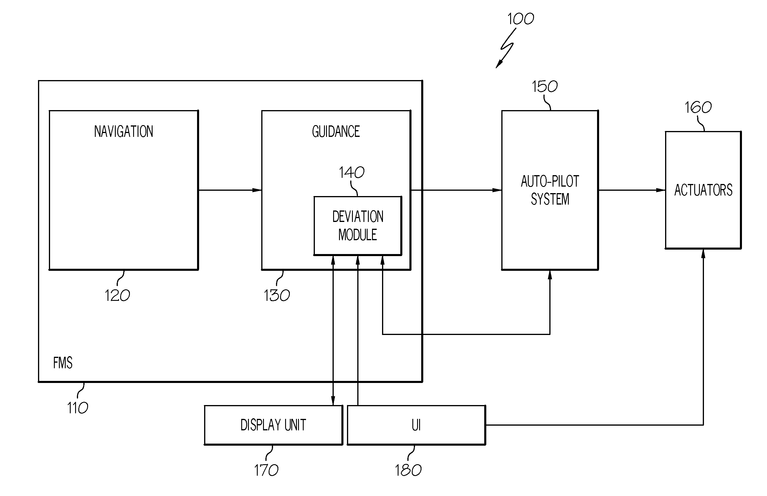
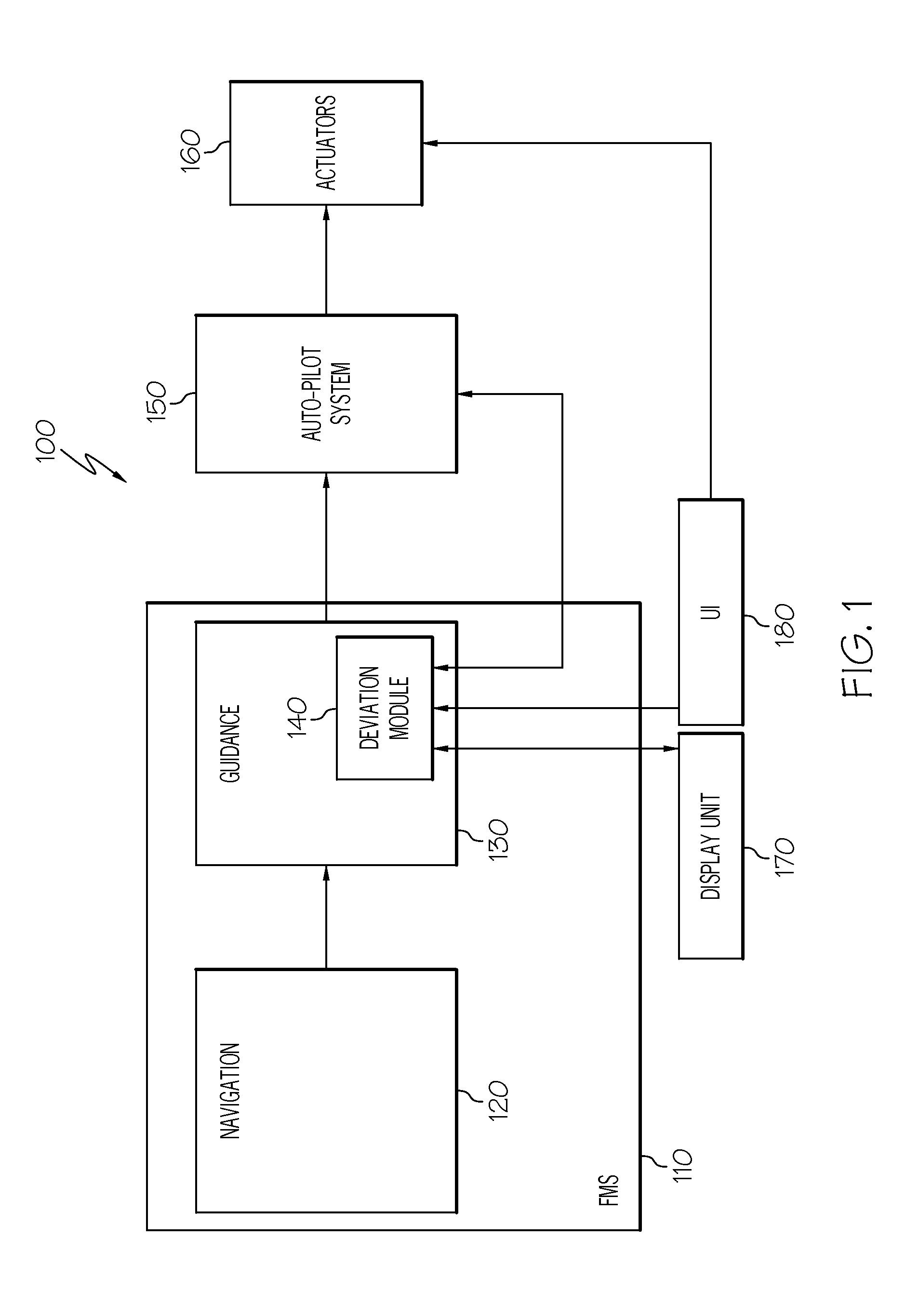
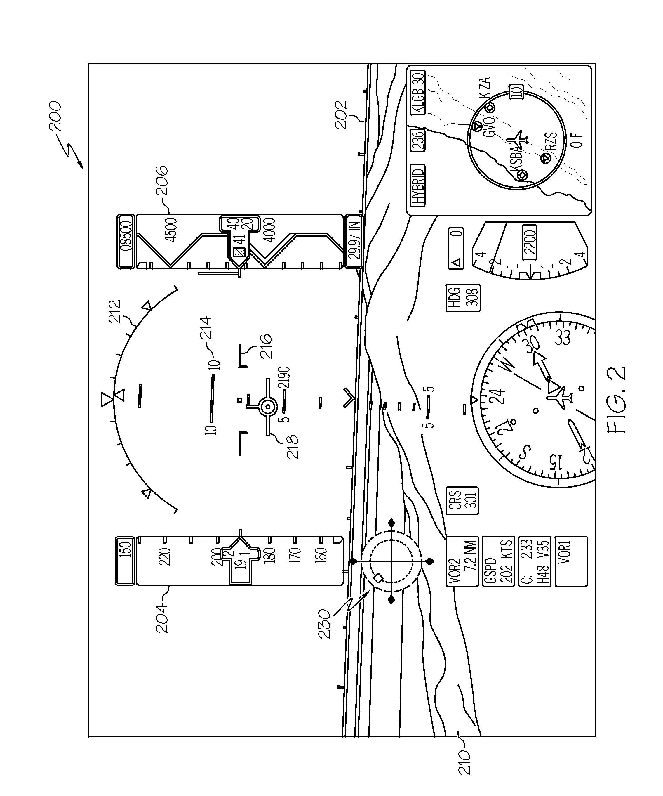
[0021]Broadly, exemplary embodiments discussed herein provide aircraft systems and methods that display improved deviation information about the current state of the aircraft relative to the fl...


PUM


Abstract

An aircraft system includes a deviation module and a visual display. The deviation module is configured to receive a flight plan with a flight segment to a waypoint, the flight plan including a lateral profile, a vertical profile, and a time profile, the time profile including a predetermined time of arrival associated with the waypoint, receive a current lateral position and a current altitude, estimate an estimated time of arrival associated with the waypoint, compare the current lateral position to the lateral profile to generate lateral deviation, compare the current altitude to the vertical profile to generate vertical deviation, and compare the predetermined time of arrival to the estimated time of arrival to generate time deviation. The visual display is coupled to the deviation module and configured to display deviation symbology representing the lateral deviation, the vertical deviation, and the time deviation.

Description

TECHNICAL FIELD[0001]The present invention generally relates to aircraft systems and methods, and more particularly relates to aircraft systems and methods that display symbology representing location, altitude, and time characteristics.BACKGROUND[0002]During aircraft operation, it is important to provide accurate and timely information to the pilot that facilitates effective flight management. The primary flight display is typically provided to display information generated by the flight management system about course, speed, altitude, rate of climb and the like. In particular, the primary flight display may display navigation information, such as a visual depiction of the trajectory according to the flight plan with respect to latitude, longitude, and altitude. Conventional systems may also display some deviation symbology that provides an indication about the current state of the aircraft relative to the anticipated state of the aircraft specified by the flight plan.[0003]More re...

Claims


Application Information

Patent Timeline
Patent Type & Authority Applications(United States)
IPC IPC(8): G01C21/00
CPCG01C23/005
Inventor GURUSAMY, SARAVANAKUMARANNAPUREDDY, VISHNU VARDHAN REDDYGAUTHAM, SANTHOSHPALANISAMY, DHIVAGARREDDY, HARICHARAN
Owner HONEYWELL INT INC
Why Eureka
Try Eureka