

Connecting rod bearing of internal combustion engine
- Summary
- Abstract
- Description
- Claims
- Application Information
AI Technical Summary
Benefits of technology
Problems solved by technology
Method used
Image

Examples
embodiment 1
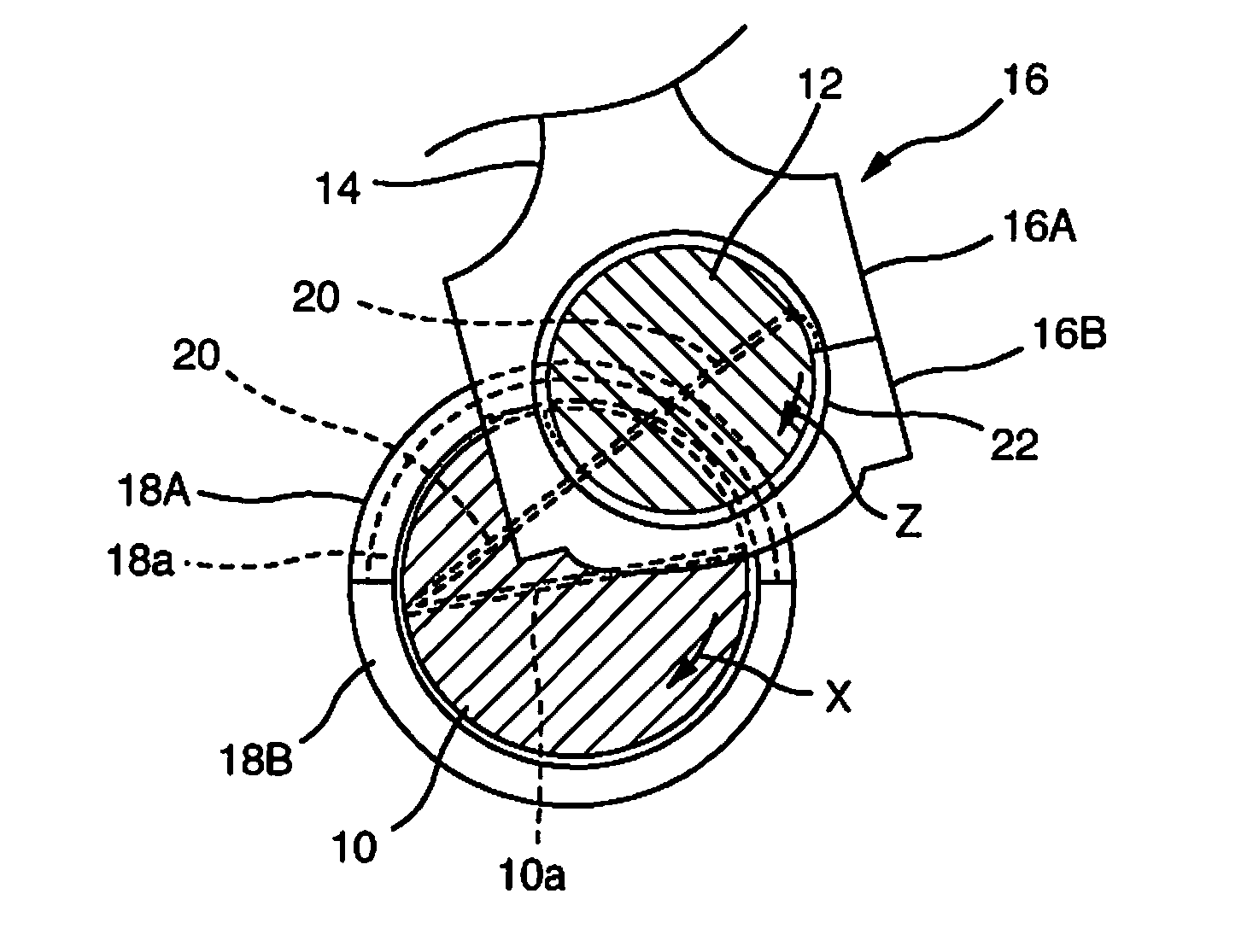
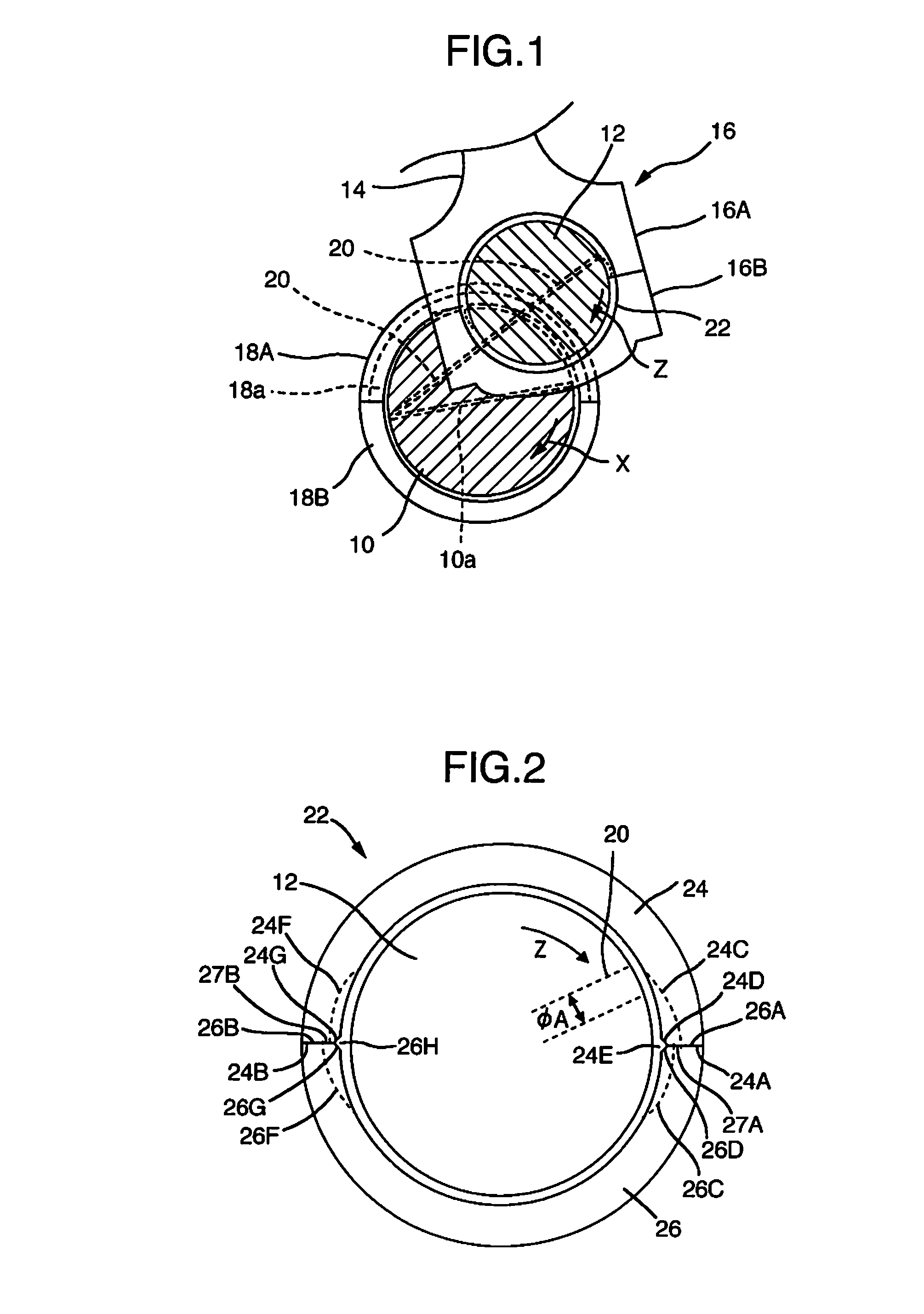
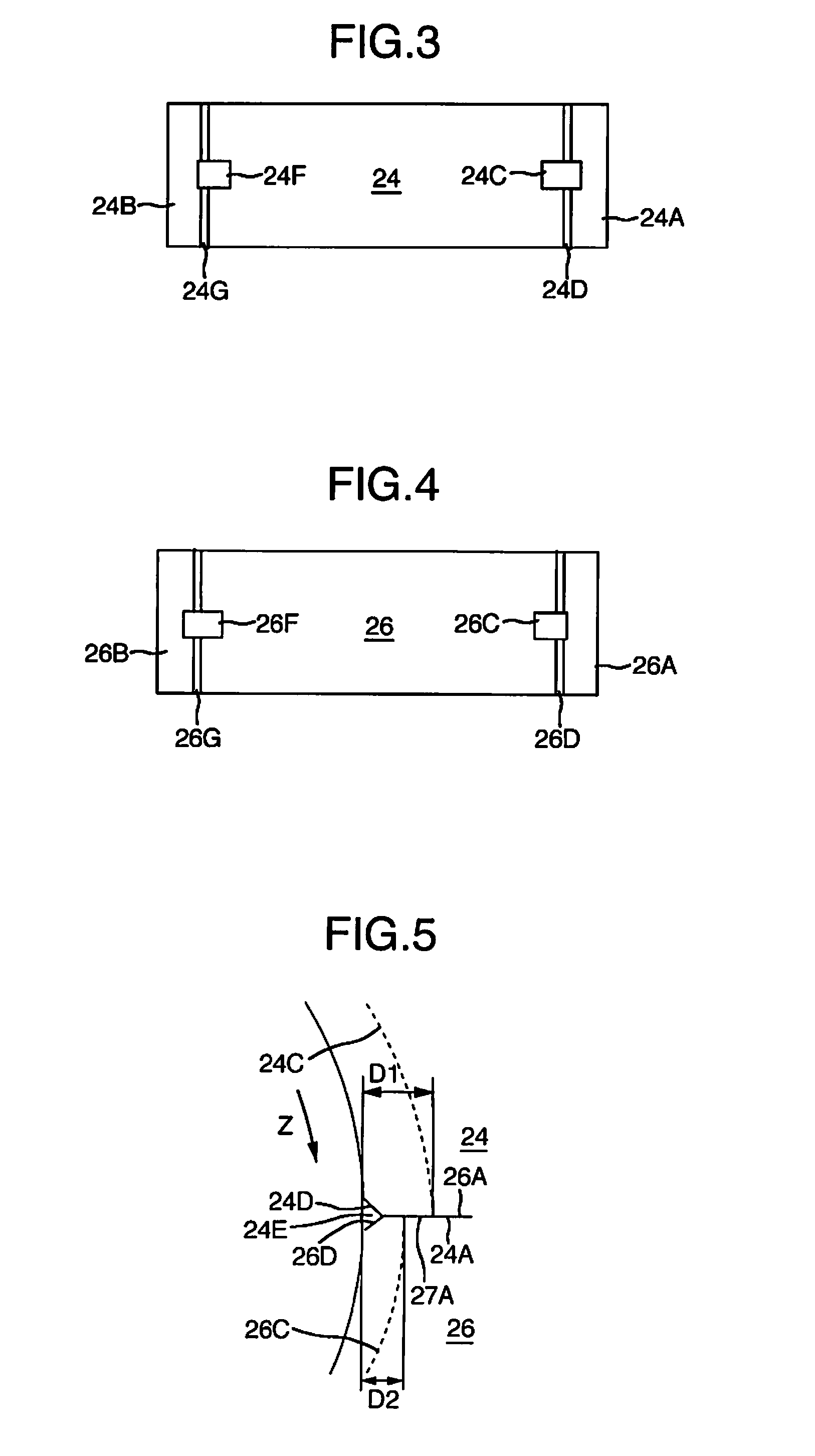
[0060]FIGS. 2 to 4 show the details of a pair of semi-cylindrical bearings 24 and 26 constituting the connecting rod bearing 22. The semi-cylindrical bearing 24 has a front side circumferential end surface 24A which is positioned at a front side with respect to a rotational direction Z of the crankpin 12, and a rear side circumferential end surface 24B which is positioned at a rear side. The semi-cylindrical bearing 26 has a front side circumferential end surface 26B which is positioned at the front side with respect to the rotational direction Z of the crankpin 12, and a rear side circumferential end surface 26A which is positioned at the rear side. The front side circumferential end surface 24A of the semi-cylindrical bearing 24 and the rear side circumferential end surface 26A of the semi-cylindrical bearing 26 abut on each other, and the front side circumferential end surface 26B of the semi-cylindrical bearing 26 and the rear side circumferential end surface 24B of the semi-cyl...
embodiment 2
[0089]FIG. 7 shows a sectional view of a communicating portion in regard with embodiment 2 of the present invention. In the embodiment, in the communicating portion, the depth (D1) of the front side circumferential groove, the depth (D2) of the rear side circumferential groove, and a depth (D3) of the axial groove satisfy the following relational expression:
[0090]the depth (D1) of the front side circumferential groove>the depth (D3) of the axial groove>the depth (D2) of the rear side circumferential groove.
[0091]In embodiment 1, the dimensional relationship of the depth (D3) of the axial groove and the depth (D2) of the rear side circumferential groove is opposite from the above, and the depth (D3) of the axial groove2) of the rear side circumferential groove is established. When the depth (D2) of the rear side circumferential groove is larger than the depth (D3) of the axial groove, some of the foreign substances, which flow in the groove bottom side of the front side circumferenti...
embodiment 3
[0093]FIGS. 8 to 11 show embodiment 3. FIG. 8 is a view of circumferential grooves and an axial groove seen from a bearing inner circumferential surface side. FIG. 9 is a view of a front side circumferential end surface seen from a circumferential direction. FIG. 10 is a view of a rear side circumferential end surface seen from the circumferential direction. FIG. 11 shows a state in which the rear side circumferential groove is seen from the front side circumferential groove.
[0094]In the present embodiment, in a communicating portion, a groove width (W1) of a front side circumferential groove 44C is larger than a groove width (W2) of a rear side circumferential groove 46C, whereby a step portion in the groove width direction of the circumferential groove is formed (see FIG. 11).
[0095]By adopting the configuration, a step portion 47C in the groove width direction is formed in addition to the step portion 47A in the depth direction of the circumferential groove, and therefore, the eff...
PUM
 Abstract
Description
Claims
Application Information