
System and method for operating a locomotive parking brake

a technology for parking brakes and locomotives, applied in braking systems, brake arrangement with braking members, transportation and packaging, etc., can solve problems such as damage to the locomotive wheel and/or parking brake, inadvertent and/or uncontrolled movement of the locomotive, and inadequate setting of the brak

Inactive Publication Date: 2013-03-21
GRAHAM WHITE MFG
View PDF9 Cites 16 Cited by
  • Summary
  • Abstract
  • Description
  • Claims
  • Application Information

AI Technical Summary

Benefits of technology

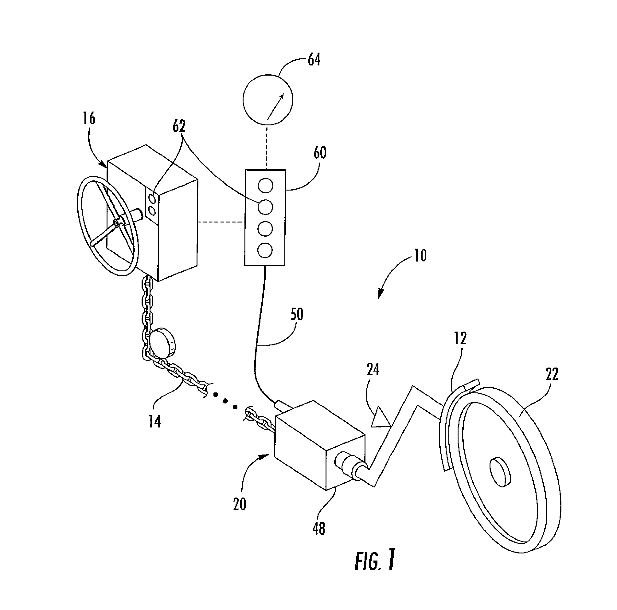
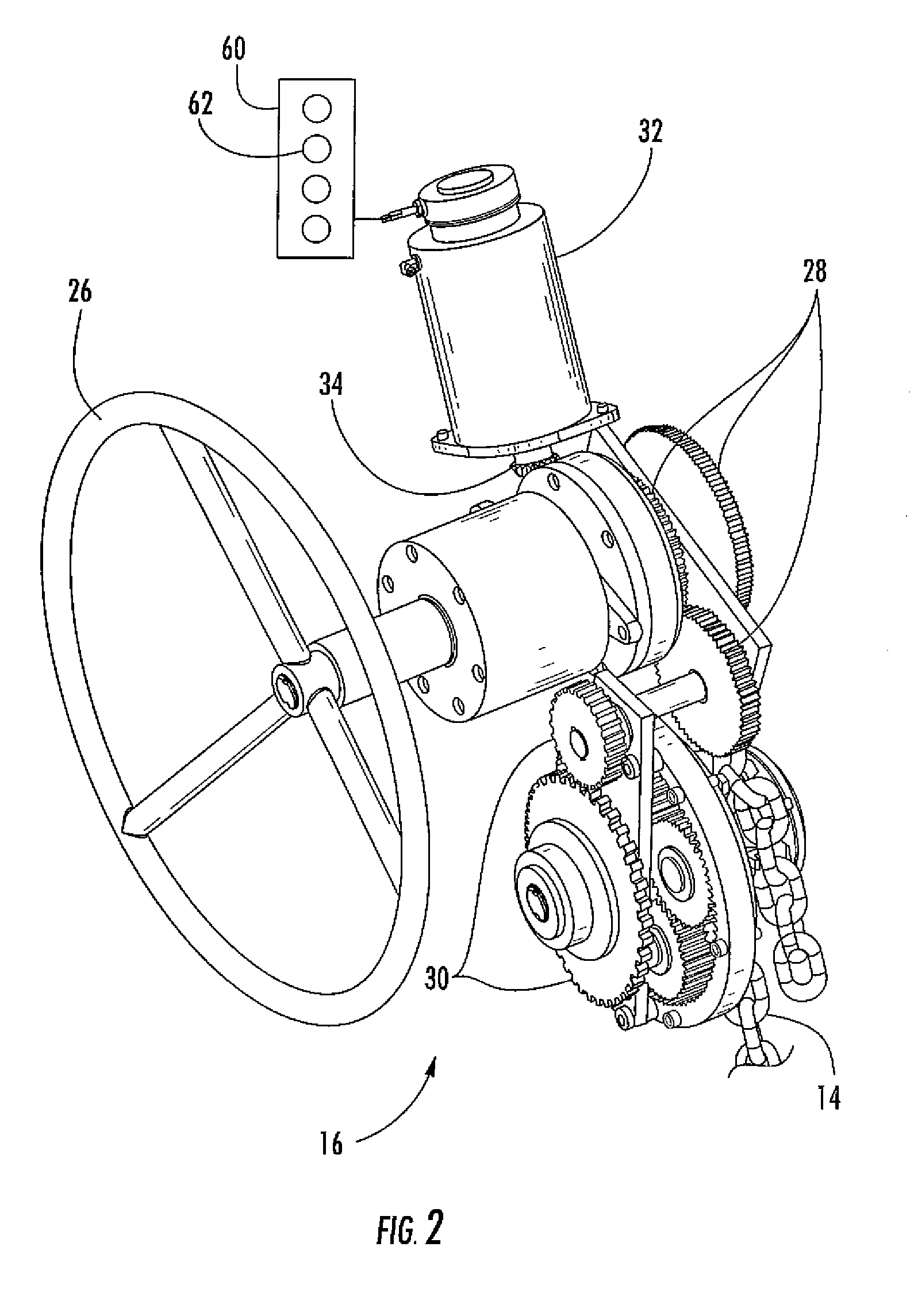
The present invention is a system for operating a locomotive parking brake that includes a wheel brake, a coupling connected to the wheel brake, and means for applying force to the coupling. The system includes a sensor connected to the coupling that measures the force applied to the coupling and generates a signal reflective of the force applied to the coupling. The system can also include a method for operating a locomotive parking brake that involves applying a force to a coupling connected to a wheel brake, measuring the force applied to the coupling, and comparing it to a predetermined limit. The technical effect of this invention is to provide a more efficient and reliable system for operating a locomotive parking brake that ensures safe and effective use.

Problems solved by technology

A parking brake that has not been adequately set may allow inadvertent and / or uncontrolled movement of the locomotive.
Conversely, a parking brake that has not been adequately released may result in damage to the locomotive wheel and / or parking brake if the locomotive is subsequently moved.
Although various devices and methods have been developed to determine the status and position of the parking brake, the remote location of the take-up device, the potential for interference with the rigging, and the general lack of direct access to the brake shoe individually and collectively can create uncertainty in the parking brake status.
As a result, the amount of force or tension applied by the take-up device and / or rigging may not accurately reflect the amount of force or tension that is actually applied by the brake shoe against the wheel.

Method used


Image

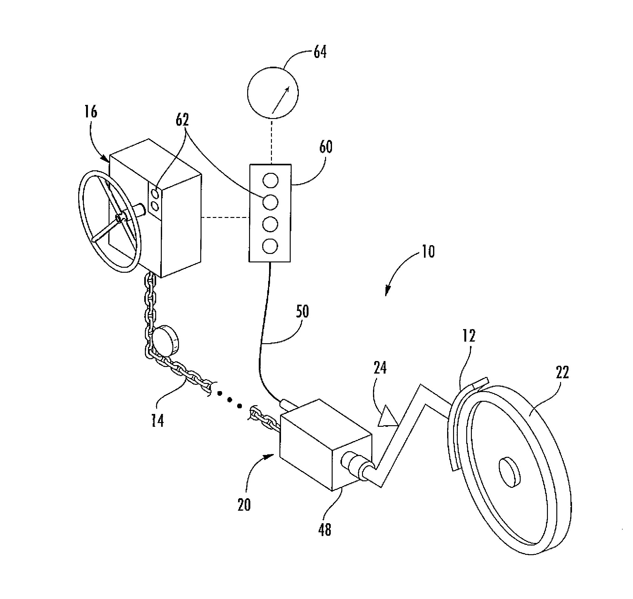
  • System and method for operating a locomotive parking brake
  • System and method for operating a locomotive parking brake
  • System and method for operating a locomotive parking brake

Examples


Embodiment Construction

[0014]Reference will now be made in detail to present embodiments of the invention, one or more examples of which are illustrated in the accompanying drawings. The detailed description uses numerical and letter designations to refer to features in the drawings. Like or similar designations in the drawings and description have been used to refer to like or similar parts of the invention. As used herein, the terms “first”, “second”, and “third” may be used interchangeably to distinguish one component from another and are not intended to signify position, location, or importance of the individual components unless specifically stated in the claims.

[0015]Each example is provided by way of explanation of the invention, not limitation of the invention. In fact, it will be apparent to those skilled in the art that modifications and variations can be made in the present invention without departing from the scope or spirit thereof. For instance, features illustrated or described as part of o...


PUM


Abstract

A system for operating a locomotive parking brake includes a wheel brake, a coupling connected to the wheel brake, and means for applying force to the coupling. A sensor connected to the coupling measures a force applied to the coupling and generates a signal reflective of the force applied to the coupling. A method for operating a locomotive parking brake includes applying a force to a coupling connected to a wheel brake, measuring the force applied to the coupling, and comparing the force applied to the coupling to a first predetermined limit. The method further includes indicating that the force applied to the coupling is equal to or greater than the first predetermined limit.

Description

FIELD OF THE INVENTION[0001]The present invention generally involves a system and method for operating a locomotive parking brake. In particular embodiments of the present invention, the system and method may detect and measure the force or tension applied by a take-up device to a wheel brake.BACKGROUND OF THE INVENTION[0002]Locomotives generally include an air brake system for stopping the locomotive and a separate parking brake system for holding the locomotive in place over long periods. For example, U.S. Pat. Nos. 6,427,811 and 7,347,306, assigned to the same assignee as the present application, disclose various embodiments of parking brakes suitable for use with locomotives. As shown in each patent, the parking brake generally includes a manual or automated take-up device connected by rigging to a brake shoe. The take-up device is often remote from the brake shoe, and operation of the take-up device applies force or tension to the rigging to draw the brake shoe directly against...

Claims


Application Information

Patent Timeline
Patent Type & Authority Applications(United States)
IPC IPC(8): B61H1/00B61H13/20B61H13/22
CPCB61H1/00B60T7/085B61H13/22B61H13/20B60T1/04F16D49/00
Inventor WEDGE, LEONARDCOLATOSTI, DAVID
Owner GRAHAM WHITE MFG
Learn More