Reflective lighting device

a technology of reflecting lighting and lighting device, which is applied in the direction of lighting device details, lighting and heating apparatus, lighting apparatus, etc., can solve the problems of more unsafe factors, energy waste, and limitations of conventional lighting devices in light efficacy, and achieve the effects of increasing the brightness and the range of illumination, and increasing the efficacy of lighting

Inactive Publication Date: 2013-03-21
JIN XIAO MING +2
View PDF5 Cites 5 Cited by
  • Summary
  • Abstract
  • Description
  • Claims
  • Application Information

AI Technical Summary

Benefits of technology

[0004]Thereby, an object of the present invention is to provide a reflective lighting device that overcomes the defects existing in the prior arts by increasing the efficacy of lighting so as to save the energy.
[0026]The light-emitting member is provided between the reflective plate and the reflective mirror. It makes the reflection of the light source become multiple reflections between the reflective plate and the reflective mirror so as to increase the brightness and the range of the illumination.
[0027]The light-emitting member passes though the double-sided mirror and is also provided among the reflective member, wherein the light-emitting member and the reflective member are in parallel with each other. The light emitted form the light source is reflected several times to become the multiple light images by the reflective member and the double-sided mirror. And the rubber ring provided on the punching hole of the double-sided mirror, which the light-emitting member passes though, is helpful for light-emitting member to be prevented from being shocked.
[0028]The surface of the triangular-prism-shaped light-emitting member is different from the surface of the conventional lamp which is circular-cylinder-shaped in the same length or the same weight condition. And the advantage of the triangular-prism-shaped light-emitting member is: It may provide the light source to be emitted with various angle because the angle of the triangular prism may be designed to be various types; The area of the surface of the triangular prism is large than that of the circular cylinder in the same cross-sectional area condition, so that the reflection area of the triangular-prism-shaped light-emitting member is larger than that of the conventional circular-cylinder-shaped lamp in the same length or the same weight condition. The increase of the reflection area also means that the efficacy of the lighting increases.
[0029]This present disclosure increases the efficacy of the lighting by increasing the reflection area so that the energy may be saved. Thereby, because of the lower energy consumption, the power source of the reflective lighting device is suitable for being supplied from the solar power device and also is able not to be transmitted with high voltage which may cause the damage and then may result in the power failure and the cost in wide regions. And particularly, the LED light is suitable for being used as the point light source of the reflective lighting device. Since the light emitted for the point-style light sources in the reflective lighting device are reflected several times to become the multiple light images, the brightness and the illumination area both increase.

Problems solved by technology

The conventional lighting device has its limitations in efficacy of light and is energy waste.
And it is necessary to use higher voltage power to cause more unsafe factors when transmitting the power.

Method used


Image

  • Reflective lighting device
  • Reflective lighting device
  • Reflective lighting device

Examples


first embodiment

The First Embodiment

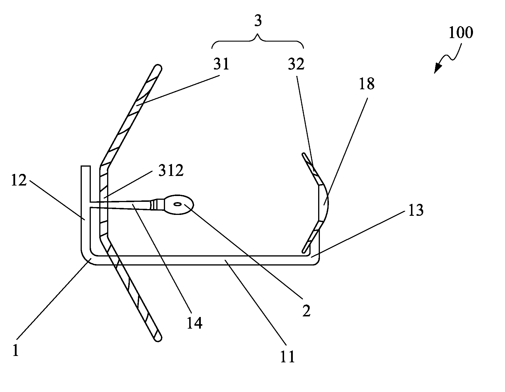
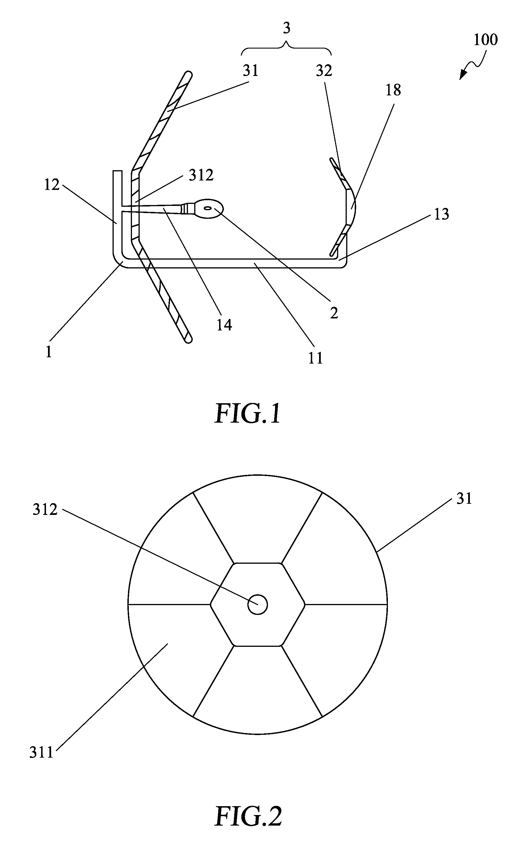
[0047]A reflective lighting device 100 of the present invention is shown in FIG. 1. A reflective plate of the reflective lighting device 100 is shown in FIG. 2. A reflective mirror plate of the reflective lighting device 100 is shown in FIG. 3. The reflective lighting device 100 comprises a supporting member 1, a light-emitting member 2, and a reflective member 3. The reflective member 3 includes a reflective plate 31 and a reflective mirror plate 32. The reflective plate 31 and the reflective mirror plate 32 are both provided on the supporting member 1. And the reflective plate 31 and the reflective mirror plate 32 face oppositely to each other. The light-emitting member 2 is disposed between the reflective plate 31 and the reflective mirror plate 32.

[0048]The supporting member 1 includes a primary rod 11, a first branch rod 12, a second branch rod 13, and a light rod 14. The first branch rod 12 and the second branch rod 13 are provided on the two ends of the pr...

second embodiment

The Second Embodiment

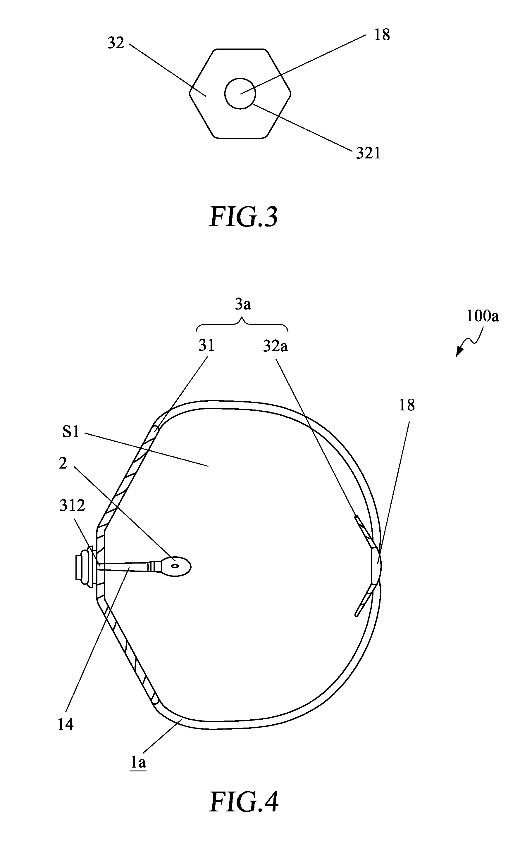
[0053]A reflective lighting device 100a of the present invention is shown in FIG. 4. A reflective mirror plate of the reflective lighting device 100a is shown in FIG. 5. The elements of this embodiment illustrated in these two Figs. are similar to those in the first embodiment. The second embodiment is different from the first embodiment in as follows. The supporting member 1a is a transparent cover. The reflective plate 31 and the reflective mirror plate 32a are provided on the two ends of the supporting member 1a respectively. The reflective mirror plate 32a includes a plurality of the reflective mirrors 322a, and a magnifying glass 18 is disposed on the edge of the aperture 321a of the reflective mirror plate 32a. The magnifying glass 18 may be fixed on the edge of the aperture 321a by interlocking. And the connection between the supporting member 1a, reflective plate 31, and the reflective mirror plate 32a is sealed and waterproof so as to form a sealed spac...

third embodiment

The Third Embodiment

[0055]A reflective lighting device 100b of the present invention is shown in FIG. 6. The elements of this embodiment illustrated in the Fig. are similar to those in the first embodiment. The third embodiment is different from the first embodiment in as follows. The reflective lighting device 100b further includes a bottom plate 15 for light rod 14 of the supporting member 1b to be disposed thereon, a plurality of the third branch rods 16 spaced at intervals and surrounding around the bottom plate 15, and a transparent plate 17 extending from the reflective mirror plate 32 and disposed on the ends of the plurality of the third branch rods 16. The reflective plate 31 is provided on the bottom plate 15 of the supporting member 1b, and the light rod 14 is inserted in the central aperture 312 of the reflective plate 31.

[0056]The illumination style of the light-emitting member 2 of this embodiment is similar to the one in the first embodiment. The third embodiment is d...


PUM


Abstract

A reflection lighting device comprises a reflective member including a reflective plate and a reflective mirror plate, and a supporting member to support the reflective member. A light-emitting member is provided between the reflective plate and the reflective mirror plate. The other reflection lighting device comprises a reflective member provided with a trough shape, and a double-sided mirror arranged within the reflective member. A light-emitting member is provided within the reflective member. And if the light-emitting member is triangular-prism-shaped, the reflection area of that is larger in the same length or the same weight condition, and the angle of the reflection surface of that is more selective, while comparing to the circular-cylinder-shaped light-emitting member which is commonly used now. Therefore, the efficiency, the intensity, and the range of the illumination increase so that the energy may be more saved.

Description

FIELD OF THE INVENTION[0001]The present invention relates to a lighting device, and more particularly to a reflective lighting device.BACKGROUND OF THE INVENTION[0002]Nowadays, the irradiation of the light emitted from the lighting device used in various places is mostly unidirectional. Therefore, there are limitations for increasing the utilization rate of the light source and for improving the efficacy of the lighting. In order to satisfy the users about the requirement of the intensity of the illumination, it is common to increase the installation quantity of the lighting device. It thus not only increases the cost expense for installation of the light device, but also it is more power consumption since it requires to use a higher voltage power. It further causes more unsafe factors which may cause the damage and then may result in the power failure in wide regions. Furthermore, since the maximum reflection area of the conventional cylinder lamp tub is limited by the area of curv...

Claims


Application Information

Patent Timeline
Patent Type & Authority Applications(United States)
IPC IPC(8): F21V7/00F21V7/04
CPCF21V7/00F21V7/0033F21V5/048F21V7/04
Inventor JIN, XIAO MINGJIN, TAOLAM, HENRY
Owner JIN XIAO MING
Why Eureka
Try Eureka