Fixing device and image forming apparatus

Active Publication Date: 2013-03-21
KONICA MINOLTA INC
View PDF1 Cites 13 Cited by
  • Summary
  • Abstract
  • Description
  • Claims
  • Application Information

AI Technical Summary

Benefits of technology

The present invention relates to a fixing device and an image forming device including it. The fixing device comprises a heating rotating body, a pressing member, and a biasing unit. The device can switch between a first state where the pressing member and the heating rotating body are in contact and a second state where they are not. The device uses one of two transmission paths for rotational power, and the power transmission targeting unit selects the path based on the direction of motor rotation. This allows for precise control of power transmission during the switching process. The technical effects of this invention include improved fixing performance and reduced power consumption during the printing process.

Problems solved by technology

As a result, if the pressing roller is continually pressed against the fixing roller, the portion of the elastic layer that elastically deforms may not fully return to its original shape if a long time passes without any images being formed.
Such a change in shape would prevent smooth transport of recording sheets.
Such a structure, however, causes the following problems to arise.
Reducing the reduction ratio, however, causes an increase in the load (torque) on the shared motor upon separation of the pressing roller (upon compression of the compression spring).
As a result, a shared motor with a high torque must be used, which increases the size of the motor, thus increasing the size of the fixing device.

Method used


Image

  • Fixing device and image forming apparatus
  • Fixing device and image forming apparatus
  • Fixing device and image forming apparatus

Examples


embodiment 1

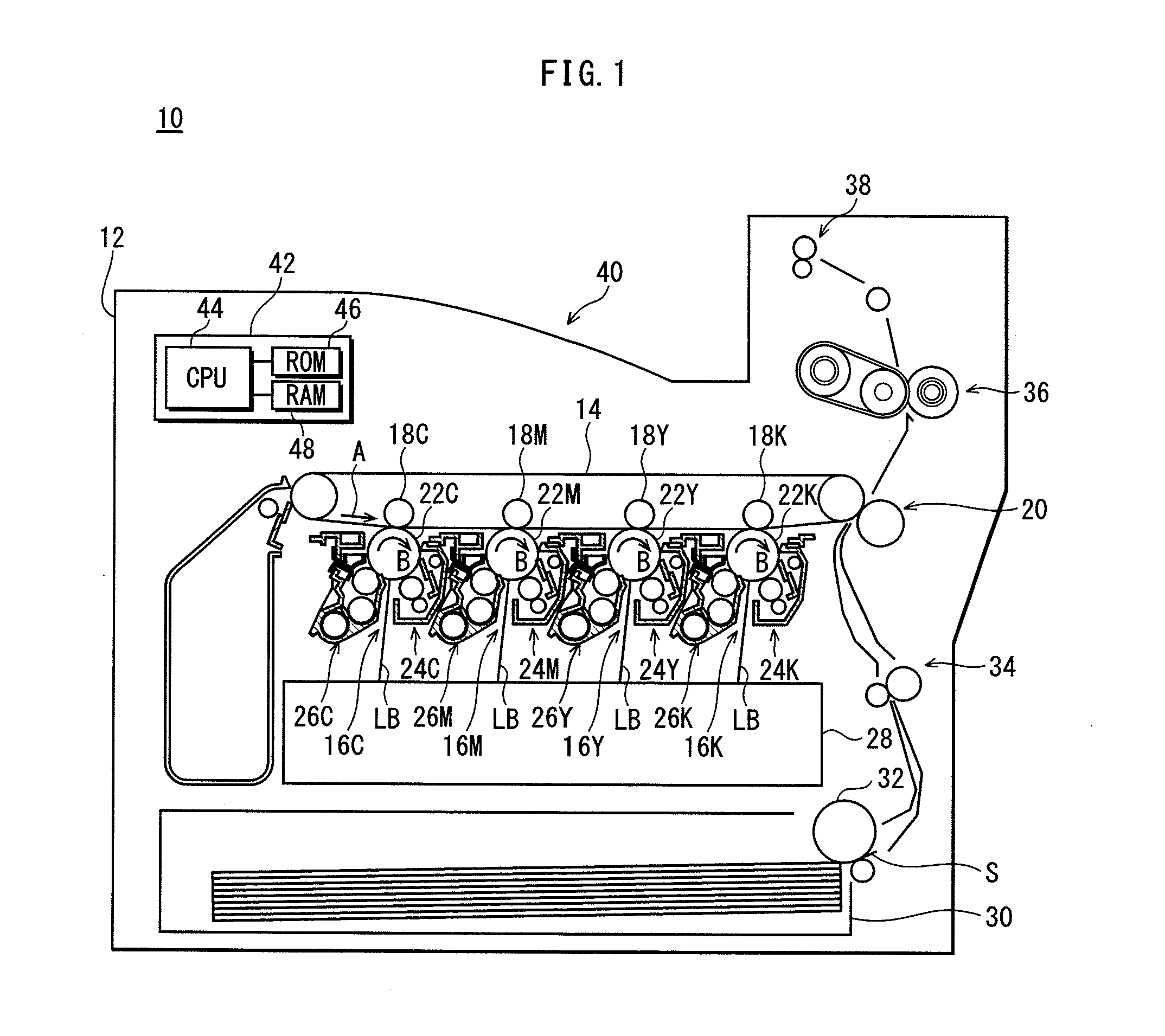
[0030]FIG. 1 illustrates the structure of a tandem-type printer 10 (hereinafter simply referred to as a “printer 10”) according to Embodiment 1. While the example of a printer is described here, the present invention is also applicable to other image forming apparatuses such as copiers, facsimile machines, and so forth.

[0031]The printer 10 is an image forming apparatus that adopts the so-called intermediate transfer method. As shown in FIG. 1, the printer 10 includes a transfer belt 14 that is provided horizontally within a housing 12 and that moves in the direction of the arrow A; four imaging units 16C, 16M, 16Y, and 16K provided in series along the direction of movement of the transfer belt 14; primary transfer rollers 18C, 18M, 18Y, and 18K that correspond to the imaging units; and a secondary transfer unit 20. Toner images of various colors formed by the imaging units 16C, 16M, 16Y, and 16K are overlaid on the transfer belt 14 and then transferred to a recording sheet S to form...

embodiment 2

[0097]In Embodiment 1, two electromagnetic clutches 144C and 152C are used in the mechanism for transmitting power from the motor 106 to the plate cam 100 (cam shaft 102). By contrast, in Embodiment 2, no electromagnetic clutches are used in the power transmission mechanism.

[0098]The fixing device of Embodiment 2 has a substantially similar structure to the fixing device 36 of Embodiment 1, except for the difference in the structure of the mechanism for transmitting power from the motor 106 to the cam shaft 102. Accordingly, similar portions are labeled with the same numbers as in Embodiment 1, and a description thereof is either omitted or simplified. The following focuses mainly on the differences.

[0099]FIG. 8 is a perspective view of a fixing device 200 in Embodiment 2, showing the structure of a mechanism for transmitting power from the motor 106 (not shown in FIG. 8; see FIG. 9) to the fixing roller 50, as well as the structure of a mechanism for transmitting power from the mot...


PUM


Abstract

A fixing device includes a heating rotating body driven by a motor, a pressing member, a biasing unit, a switching unit that receives rotational power of the motor in order to either separate the pressing member and the heating rotating body or to allow the biasing unit to press the pressing member and the heating rotating body together, a power transmission mechanism that transmits the rotational power of the motor to the switching unit over a first path or a second path, the first path having a larger reduction ratio, and a power transmission targeting unit that switches the target of transmission of rotational power of the motor between the heating rotating body and the switching unit depending on the rotational direction of the motor and that includes a path selection unit that selects the first path during separation and the second path during pressing by the switching unit.

Description

[0001]This application is based on application No. 2011-204484 filed in Japan, the contents of which are hereby incorporated by reference.BACKGROUND OF THE INVENTION[0002](1) Field of the Invention[0003]The present invention relates to a fixing device and an image forming apparatus, and in particular to a fixing device and an image forming apparatus provided with the fixing device that have a structure allowing for switching of a pressing member between a pressing state and a separated state with respect to a heating rotating body of a fixing roller or the like.[0004](2) Description of the Related Art[0005]In image forming apparatuses such as printers, a fixing device that uses a heat fixing method fixes toner to a recording sheet in the following way. For example, a pressing roller, which acts as a pressing member, is pressed against the circumferential surface of a rotating fixing roller by the restorative force of an elastic member such as a compression spring, thereby forming a ...

Claims


Application Information

Patent Timeline
IPC IPC(8): G03G15/20
CPCG03G21/1685G03G15/2092
Inventor FUJIWARA, TAKASHIYOSHIKAWA, SHOICHISEKIOKA, TADAYASUOOMOTO, NOBORUTOSO, YOSHIYUKIMIYAGAWA, NAOKI
Owner KONICA MINOLTA INC
Why Eureka
Try Eureka