There have been reports of latent problems with cardiac pacemakers or other AIMDs after an MRI procedure sometimes occurring many days later.
Moreover, there are a number of recent papers that indicate that the SAR level is not entirely predictive of the heating that would be found in implanted lead wires or devices.
It is speculated that SAR level alone is not a good predictor of whether or not an
implanted device or its associated lead wire
system will overheat.
These antennas are not very efficient due to the damping effects of
body tissue; however, this can often be offset by extremely high power fields (such as MRI pulsed fields) and / or body resonances.
There are a number of potential problems with MRI, including: (1) Closure of the pacemaker
reed switch.
Direct damage to the reed switch is theoretically possible, but has not been reported in any of the known literature.
Some parts of pacemakers, such as the batteries and reed switch, contain
ferrous magnetic materials and are thus subject to mechanical forces during MRI.
The effects of this heating are not readily detectable by monitoring during the MRI.
Such long term heating effects of MRI have not been well studied yet for all types of AIMD lead wire geometries.
There can also be localized heating problems associated with various types of electrodes in addition to TIP electrodes.
It has been observed that the
RF field may induce undesirable fast pacing (QRS complex) rates.
The contribution of the time-varying gradient to the
total strength of the MRI
magnetic field is negligible, however, pacemaker systems could be affected because these fields are rapidly applied and removed.
There are additional problems possible with implantable cardioverter defibrillators (ICDs).
ICDs use different and larger batteries which could cause higher magnetic forces.
The programmable sensitivity in ICDs is normally much higher (more sensitive) than it is for pacemakers, therefore, ICDs may falsely detect a
ventricular tachyarrhythmia and inappropriately deliver therapy.
There can also be heating problems of ICD leads which are expected to be comparable to those of
pacemaker leads.
That is, during an MRI procedure, if they inadvertently sense the MRI fields as a dangerous ventricular arrhythmia, the ICD will attempt to charge up and deliver a
high voltage shock.
This makes it highly unlikely that an ICD patient undergoing an MRI would receive an inappropriate
high voltage shock therapy.
While ICDs cannot charge during MRI due to the saturation of their ferro-magnetic transformers, the battery will be effectively shorted and lose life.
This is a highly undesirable condition.
In summary, there are a number of studies that have shown that MRI patients with active implantable medical devices, such as cardiac pacemakers, can be at risk for potential hazardous effects.
These anecdotal reports are of interest, however, they are certainly not scientifically convincing that all MRI can be safe.
In a typical AM and FM radio in an automobile, these
wavelength signals would not efficiently couple to the relatively short antenna of a
cell phone.
There are certain implanted lead wire lengths that just do not couple efficiently with the MRI frequency and there are others that would couple very efficiently and thereby produce the worst case for heating.
Most experts still conclude that MRI for the pacemaker patient should not be considered safe.
As MRI technology progresses, including higher field gradient changes over time applied to thinner tissue slices at more rapid imagery, the situation will continue to evolve and become more complex.
However, some implantable pumps work on
magneto-peristaltic systems, and must be deactivated prior to MRI.
There are newer (unreleased) systems that would be based on solenoid systems which will have similar problems.
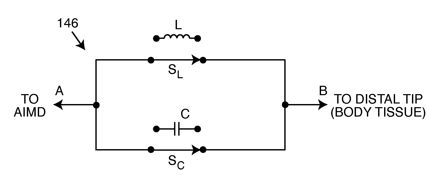
As one can see, many of the undesirable effects in an implanted lead wire
system from MRI and other
medical diagnostic procedures are related to undesirable induced currents in the lead wire
system and / or its distal TIP (or RING).
This can lead to overheating either in the lead wire or at the
body tissue at the distal TIP.

