
Composite RF current attenuator for a medical lead

Active Publication Date: 2012-10-04
WILSON GREATBATCH LTD
View PDF2 Cites 63 Cited by
  • Summary
  • Abstract
  • Description
  • Claims
  • Application Information

AI Technical Summary

Benefits of technology

[0034]The medical lead may comprise an epicardial lead, a split-cylinder, a cuff electrode, a self-sizing nerve cuff, a multiple-cuff nerve electrode, a multiple bandstop filter array, a deep brain electrode, a paddle electrode, a Pad electrode, a deep brain stimulating array, a Ring electrode, an active fixation Tip electrode, a passive fixation Tip electrode, a lead extension electrode, a probe, a catheter or an ablation probe. Electrical insulation may be provided for preventing or inhibiting stray RF currents in the body fluids and tissues from degrading the impedance of the bandstop filter and / or the lowpass filter at resonance
[0035]In the case where the bandstop filter is formed as at least a part of a coiled or spiral inductor portion of the lead conductor, and the capacitance is the parasitic capacitance formed between adjacent turns of said inductor portion, electrical insulation may be provided for preventing RF currents and body fluids or tissues from degrading the impedance of the lowpass filter or the bandstop filter at resonance. The electrical insulation typically comprises an insulative sleeve disposed about the coiled or spiral inductor portion of the conductor. The coiled or spiral inductor portion of the lead conductor may have separate distinct segments having different inductance and parallel capacitance values to form a plurality of bandstop filters which resonate at multiple different selected center frequencies. More specifically, the coiled or spiral inductor portion of the lead conductor may include distinct segments having different numbers of turns to form distinct bandstop filters which resonate at different selected center frequencies or across different ranges of frequencies.
[0044]The QI of the inductor portion may be inversely proportioned to the QC of the capacitance to select the overall Q of the bandstop filter. The QI of the inductor portion is increased by reducing resistive loss in the inductor portion and the QI of the conductor portion is decreased by increasing resistive loss in the inductor. The QC of the capacitance is reduced by raising the equivalence series resistance of the capacitance, and the QC of the capacitance is increased by lowering the equivalent series resistance of the capacitance.

Problems solved by technology

Compatibility of cardiac pacemakers, implantable defibrillators and other types of active implantable medical devices with magnetic resonance imaging (MRI) and other types of hospital diagnostic equipment has become a major issue.
There have been reports of latent problems with cardiac pacemakers or other AMDs after an MRI procedure, sometimes occurring many days later.
Moreover, there are a number of recent papers that indicate that the SAR level is not entirely predictive of the heating that would be found in implanted lead wires or devices.
It is speculated that SAR level alone is not a good predictor of whether or not an implanted device or its associated lead wire system will overheat.
These antennas are not very efficient due to the damping effects of body tissue; however, this can often be offset by extremely high power fields (such as MRI RF pulsed fields) and / or body resonances.
The effects of this heating are not readily detectable by monitoring during the MRI.
Such long term heating effects of MRI have not been well studied yet for all types of AIMD lead wire geometries.
There can also be localized heating problems associated with various types of electrodes in addition to Tip electrodes.
There are additional problems possible with implantable cardioverter defibrillators (ICDs).
The programmable sensitivity in ICD biological sense circuits is normally much higher (more sensitive) than it is for pacemakers; therefore, ICDs may falsely detect a ventricular tachyarrhythmia and inappropriately deliver therapy.
There can also be heating problems of ICD leads which are expected to be comparable to those of pacemaker leads.
This makes it highly unlikely that an ICD patient undergoing an MRI would receive an inappropriate high voltage shock therapy.
While ICDs cannot charge during MRI due to the saturation of their ferro-magnetic transformers, the battery will be effectively shorted and lose life.
This is a highly undesirable condition.
In summary, there are a number of studies that have shown that MRI patients with active medical devices, such as cardiac pacemakers, can be at risk for potential hazardous effects.
These anecdotal reports are of interest, however, they are certainly not scientifically convincing that all MRI can be safe.
In a typical AM and FM radio in an automobile, these wavelength signals would not efficiently couple to the relatively short antenna of a cell phone.
There are certain implanted lead wire lengths that do not couple efficiently with the MRI frequency and there are others that would couple very efficiently and thereby produce the worst case for heating.
Most experts still conclude that MRI for the pacemaker patient should not be considered safe.
As MRI technology progresses, including higher field gradient changes over time applied to thinner tissue slices at more rapid imagery, the situation will continue to evolve and become more complex.
As one can see, many of the undesirable effects in an implanted lead system from MRI and other medical diagnostic procedures are related to undesirable induced currents in the conductor(s) of the lead system and / or its distal Ring electrode (or Ring).
This can lead to overheating either in the lead or at the body tissue at the distal Ring electrode.
Accordingly, it is difficult to predict to what static magnetic field strength scanner an AIMD patient may eventually be exposed.

Method used


Image

  • Composite RF current attenuator for a medical lead
  • Composite RF current attenuator for a medical lead
  • Composite RF current attenuator for a medical lead

Examples


Embodiment Construction

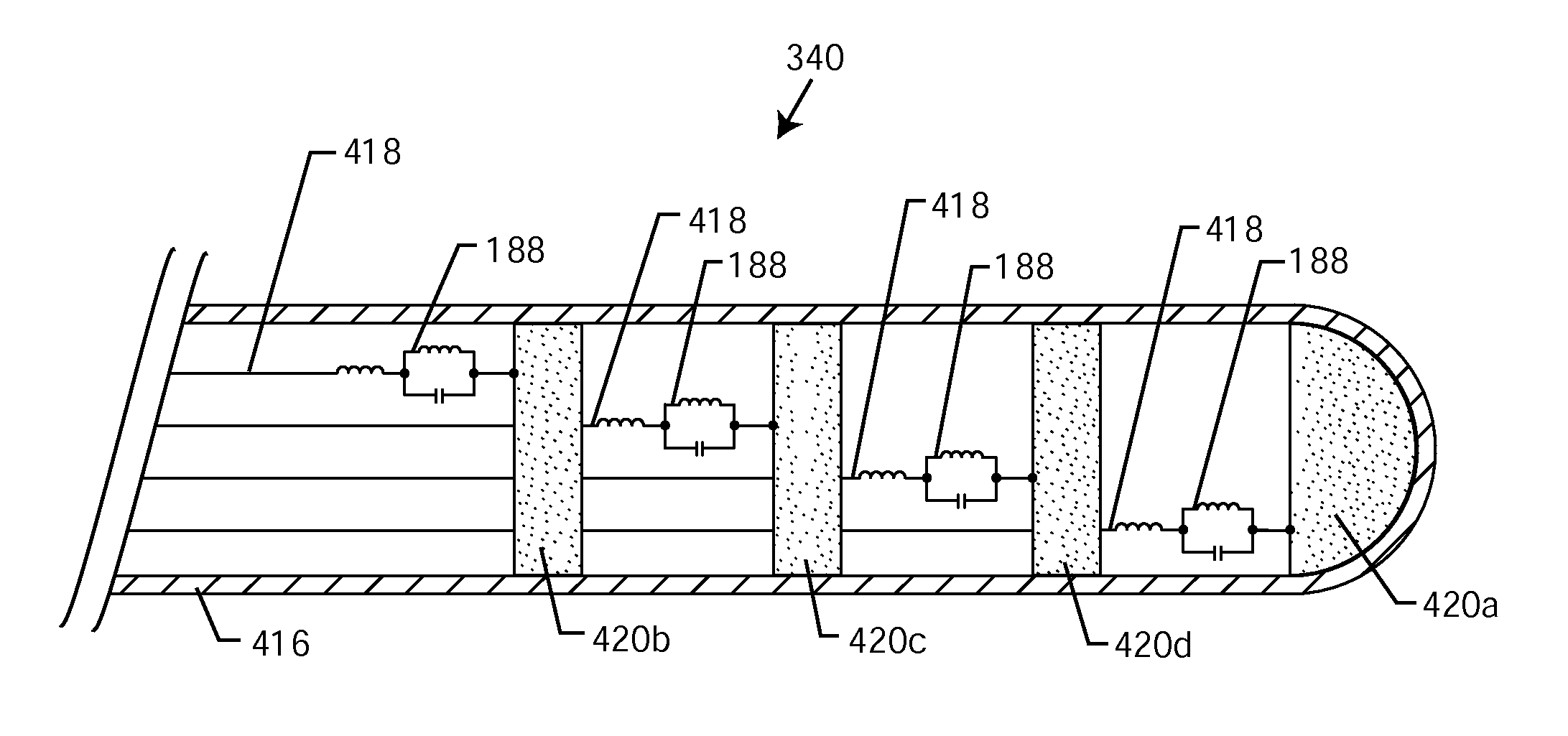
[0156]The present invention is directed to medical lead systems comprising an implantable lead having a proximal end and an electrode contactable to biological cells at a distal end. At least one broadband lowpass filter, such as an inductor is disposed in series with a bandstop filter and is associated with a lead conductor forming a composite RF current attenuator for attenuating current flow through the lead over a range of RF frequencies. In general, the broadband lowpass filter can consist of an inductor, L, LL, Pi, T-filter or multi-element filter or the like. The bandstop filter, which is in series with the lowpass filter, has an overall circuit Q wherein the resultant 3 dB bandwidth is at least 10 kHz and where the bandstop filter comprises a capacitance in parallel with an inductance, wherein values of capacitance and inductance are selected such that the bandstop filter is resonant at a selected center frequency. The selected center frequency is an MRI RF pulsed frequency....


PUM


Abstract

A composite RF current attenuator for a medical lead includes a conductor having a distal electrode contactable to biological cells, a bandstop filter in series with the lead conductor for attenuating RF currents flow through the lead conductor at a selected center frequency or across a range of frequencies about the center frequency, and a lowpass filter in series with the bandstop filter and forming a portion of the lead conductor. The bandstop filter has a capacitance in parallel with a first inductance. In a preferred form, the lowpass filter includes a second inductance in series with the bandstop filter, wherein the values of capacitance and inductances for the composite RF current attenuator are selected such that it attenuates MRI-induced RF current flow in an MRI environment.

Description

FIELD OF THE INVENTION[0001]This invention relates generally to novel composite RF current attenuators for a medical lead comprising series lowpass and bandstop broadband filter assemblies, particularly of the type used in the implantable leads of active medical devices (AMDs) such as cardiac pacemakers, cardioverter defibrillators, neurostimulators, externally worn Holter monitors and the like. The bandstop filter portion of the composite RF current attenuator provides a very high impedance at the selected MRI RF center frequency and / or a range of frequencies about the center frequency. This works in concert with the composite lowpass filter which provides high impedance at higher MRI RF frequencies.BACKGROUND OF THE INVENTION[0002]Compatibility of cardiac pacemakers, implantable defibrillators and other types of active implantable medical devices with magnetic resonance imaging (MRI) and other types of hospital diagnostic equipment has become a major issue. If one goes to the webs...

Claims


Application Information

Patent Timeline
IPC IPC(8): A61N1/05A61B18/00
CPCA61B5/042A61B5/055A61B18/1492A61B2018/00839A61B2019/5236A61B2562/182H03H2007/013A61B2562/227A61N1/05A61N1/3718A61N2001/086H03H1/0007H03H2001/0021A61B2562/222A61B2090/374A61N1/086A61B5/283H03H7/0123
Inventor STEVENSON, ROBERT A.JOHNSON, ROBERT SHAWNKONDABATNI, KISHORE KUMARSPAULDING, JOSEPHFRUSTACI, DOMINICK J.DABNEY, WARREN S.MOSCHIANO, HOLLY NOELLE
Owner WILSON GREATBATCH LTD
Learn More