
Switched reluctance motor

Inactive Publication Date: 2013-03-28
SAMSUNG ELECTRO MECHANICS CO LTD
View PDF1 Cites 12 Cited by
  • Summary
  • Abstract
  • Description
  • Claims
  • Application Information

AI Technical Summary

Benefits of technology

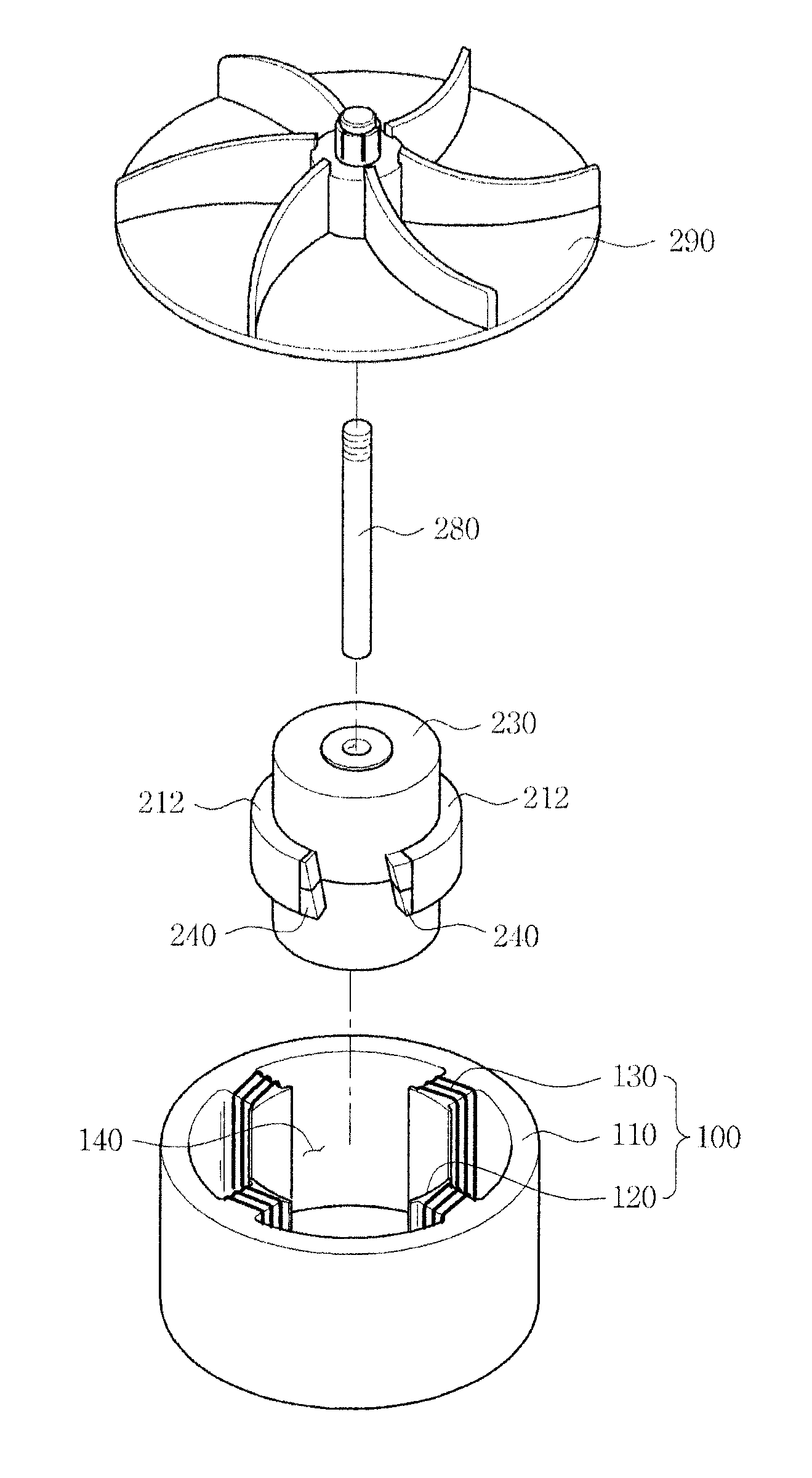
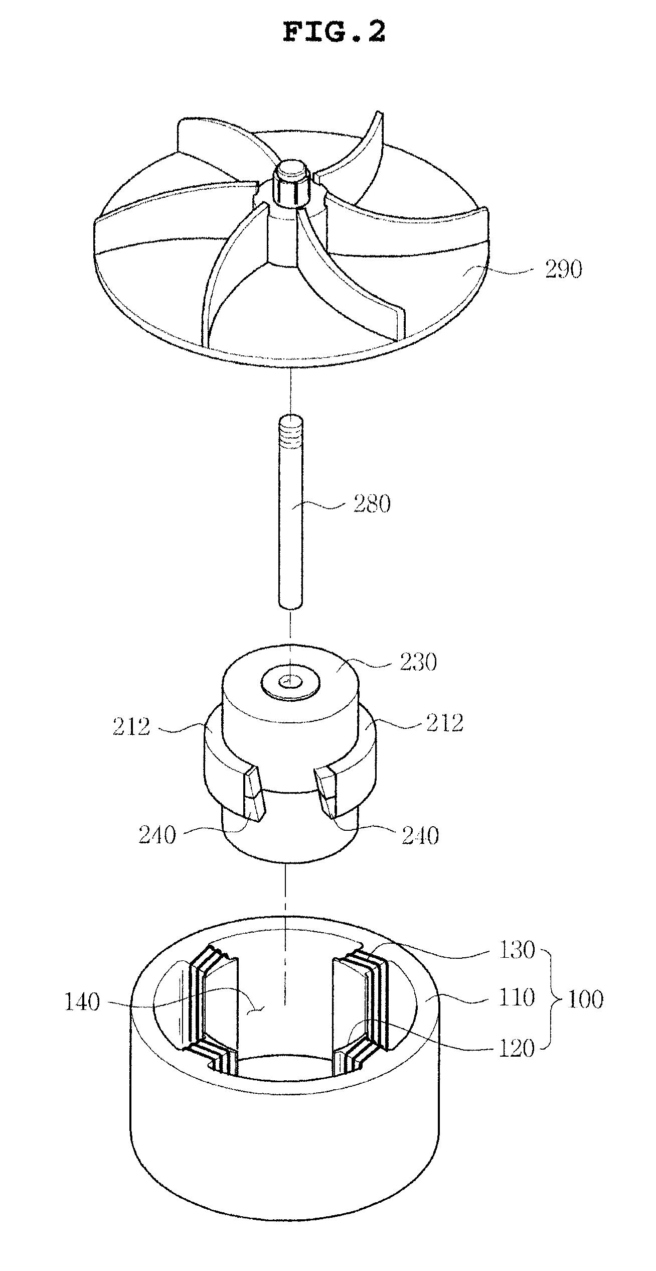
The present invention provides a switched reluctance motor with a blade part between the rotor salient poles to generate fluid flow in a direction of a shaft. The blade part includes a first blade body and a second blade body, each with a hollow hole for the shaft, and a plurality of blades formed to be protruded from the blade bodies. The blade part can be connected to the rotor in a vertical manner to improve motor performance. The blade part can also have a concave or convex surface to improve fluid flow and motor performance.

Problems solved by technology

This switched reluctance motor has a cheap cost, such that it may be used in various industrial fields.
However, in the case in which the switched reluctance motor according to the related art is operated for a long period of time, significant heat is generated at an inner portion of the motor, such that the motor is damaged.
In addition, air circulation is conducted at the inner portion of the motor to some degree by rotation of the rotor 20, which has a limitation in spontaneously cooling heat generated at the inner portion of the motor.
As a result, cooling characteristics of the motor are deteriorated, and reliability of a product be also deteriorated.
Further, when the switched reluctance motor is used in a product having a function of sucking external fluid such as a vacuum cleaner, there is a problem in providing a predetermined level of required fluid suction force.
Furthermore, in the case of increasing rotational force of the motor in order to increase the fluid suction force, the motor is further overheated to be damaged.

Method used


Image

  • Switched reluctance motor
  • Switched reluctance motor
  • Switched reluctance motor

Examples


Embodiment Construction

[0048]Various objects, advantages and features of the invention will become apparent from the following description of embodiments with reference to the accompanying drawings. In the specification, in adding reference numerals to components throughout the drawings, it is to be noted that like reference numerals designate like components even though components are shown in different drawings. Further, terms used in the specification, ‘first’, ‘second’, etc. can be used to describe various components, but the components are not to be construed as being limited to the terms. The terms are only used to differentiate one component from other components. Further, when it is determined that the detailed description of the known art related to the present invention may obscure the gist of the present invention, the detailed description thereof will be omitted.

[0049]Hereinafter, preferred embodiments of the present invention will be described in detail with reference to the accompanying draw...


PUM


Abstract

Disclosed herein is a switched reluctance motor including: a stator part including a plurality of salient poles formed at an inner peripheral surface thereof and coils wound around the salient poles; and a rotor part rotatably inserted into an inner portion of the stator part to thereby rotate in one direction by a reluctance torque, wherein the rotor part includes: a rotor including a rotor core provided with a shaft hole into which a shaft is inserted and a plurality of rotor salient poles formed to be protruded from the rotor core so as to face the salient poles of the stator part; and a blade part disposed between the rotor salient poles to thereby generate a fluid flow in a direction of the shaft.

Description

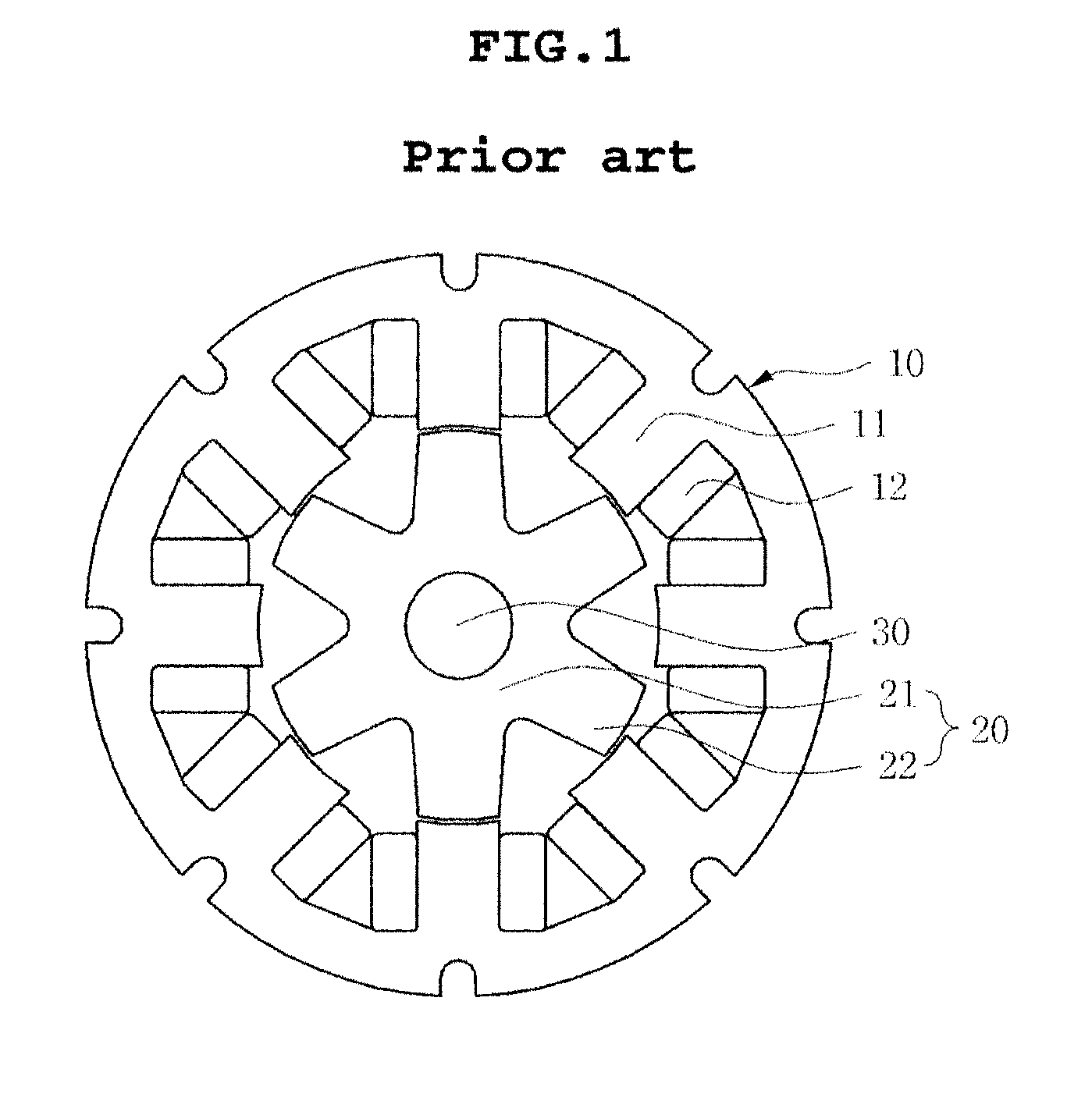
CROSS REFERENCE TO RELATED APPLICATION[0001]This application claims the benefit of Korean Patent Application No. 10-2011-0098182, filed on Sep. 28, 2011, entitled “Switched Reluctance Motor”, which is hereby incorporated by reference in its entirety into this application.BACKGROUND OF THE INVENTION[0002]1. Technical Field[0003]The present invention relates to a switched reluctance motor.[0004]2. Description of the Related Art[0005]Generally, a switched reluctance motor is configured to include a stator part 10 including a plurality of fixed salient poles 11 and a rotor 20 including a plurality of rotating salient poles 22 facing the plurality of fixed salient poles 11 as shown in FIG. 1.[0006]More specifically, the stator part 10 is configured to include the plurality of fixed salient poles 11 formed to be protruded at predetermined intervals in a circumferential direction of an inner peripheral surface thereof so as to face the rotor 20 and coils 12 wound around each of the fixed s...

Claims


Application Information

Patent Timeline
IPC IPC(8): H02K9/06
CPCF04D25/0606H02K1/246H02K19/103H02K9/06H02K7/14H02K19/10
Inventor PARK, CHANG HWANYUN, TAE HOYOON, YOUNG BOKLEE, SANG JONGYOON, HEE SOOBAE, HAN KYUNGJANG, SU BONG
Owner SAMSUNG ELECTRO MECHANICS CO LTD
Learn More