
Tubing retrievable injection valve assembly

a technology of injection valve and assembly, which is applied in the field of injection valve, can solve problems such as harm to the flapper valve assembly, and achieve the effect of reducing the pressure drop during injection

Active Publication Date: 2013-04-04
TEJAS RES & ENG
View PDF13 Cites 20 Cited by
  • Summary
  • Abstract
  • Description
  • Claims
  • Application Information

AI Technical Summary

Benefits of technology

This patent describes a device that can be used in oil and gas wells to control the flow of fluids. The device includes a valve and a nozzle that can be easily installed and removed without needing to remove the entire valve. The nozzle has a variable orifice to control the pressure drop during injection, which helps to minimize harmful effects on the valve assembly. Overall, this device allows for easier and more efficient well construction.

Problems solved by technology

This prevents the flapper valve from “chattering” and isolates the flapper valve from fluid flow during injection both of which are harmful to the flapper valve assembly.

Method used


Image

  • Tubing retrievable injection valve assembly
  • Tubing retrievable injection valve assembly
  • Tubing retrievable injection valve assembly

Examples


Embodiment Construction

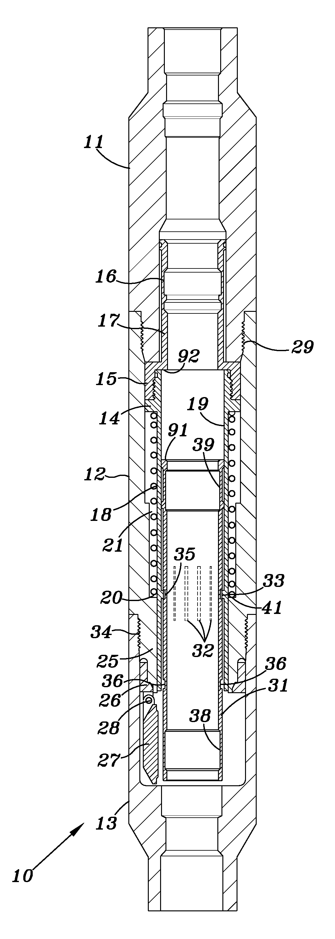
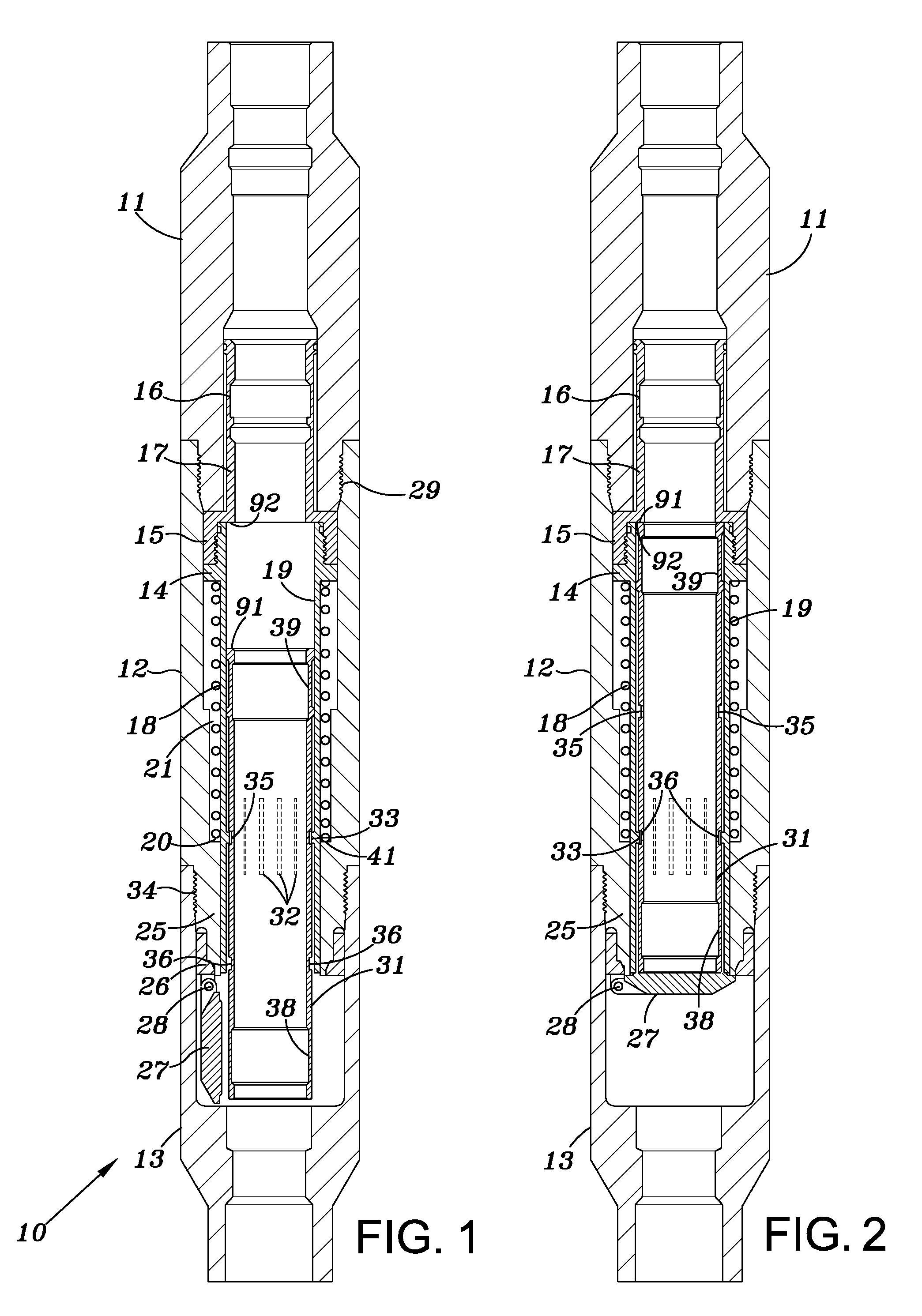
[0024]Referring to FIG. 1, an embodiment of the injection valve 10 includes a pressure containing body comprising an upper valve body member 11, a tubular middle valve body member 12 suitably attached to the upper valve body member 11 by threads at 29, for example, and a lower valve body member 13 which is connectable to a tubular at its downhole end. Valve body members 12 and 13 are secured to each other by threads for example at 34.

[0025]The injection valve 10 further includes an upper flow tube having a first section 17 and a second section 14 which are secured together. Section 17 has an interior nipple profile at 16 for receiving a tool. Section 14 has an elongated sleeve portion 19 that extends to valve seat 26 when the valve is in the position shown in FIG. 1. Elongated sleeve portion 19 includes a plurality of slots 32 as shown in FIG. 1. Ridges 33 are formed on the inner surface of sleeve 19 around slots 32 thus forming a collet. A shiftable lower flow tube 31 is positioned...


PUM


Abstract

A method and apparatus for controlling the flow of fluid in an injection well includes a main valve assembly having a valve and a retrievable nozzle selective lock assembly (RNSLA). The RNSLA is operable when positioned within the valve body to open the valve when fluid is pumped into the well and closes the valve when fluid flow is terminated. The RNSLA includes a replaceable orifice nozzle so that orifices of different dimensions may be used in conjunction with the valve assembly. In an alternate embodiment, the RNSLA includes a variable output nozzle assembly to maintain the valve in a protected open position without chattering over a wide range of flow rates.

Description

[0001]This application claims priority to provisional application Ser. No. 61 / 639,569 with a filing date of Apr. 27, 2012.BACKGROUND OF INVENTION[0002]1. Field of the Invention[0003]This invention is directed to an injection valve typically used in conjunction with an injection well. Injection wells are drilled for example in close proximity to producing oil or gas wells that have peaked in terms of their output. Fluid for example water is pumped under pressure into the injection well which in turn acts to force the oil or gas into the producing wells thus increasing the yield.[0004]2. Description of Related Art[0005]U.S. Pat. No. 7,966,401 discloses an injection safety valve having a restrictor to create a pressure differential so as to move a flow tube past a flapper valve. The diameter of the restrictor if fixed.BRIEF SUMMARY OF THE INVENTION[0006]The invention includes providing a tubing retrievable injection valve having a full bore internal diameter when running and retrieving...

Claims


Application Information

Patent Timeline
Patent Type & Authority Applications(United States)
IPC IPC(8): E21B34/10
CPCE21B34/102E21B34/10E21B43/16E21B43/20G16H40/63E21B2200/05
Inventor HILL, JR., THOMAS G.HENSCHEL, ROBERT C.HODGE, RORY L.PFAFF, SHANE W.
Owner TEJAS RES & ENG
Learn More