Layered thermal store with selectively alterable gas flow path

a gas flow path and thermal storage technology, applied in the field of thermal storage apparatus, can solve problems such as considerable pressure drop, and achieve the effect of improving system efficiency and being convenient to opera

Inactive Publication Date: 2017-05-23
ENERGY TECH INST
View PDF45 Cites 32 Cited by
  • Summary
  • Abstract
  • Description
  • Claims
  • Application Information

AI Technical Summary

Benefits of technology

[0024]As the gas flows through the storage media in order for thermal transfer to occur, there is a pressure drop associated with this constrained flow. In very large thermal stores, this can be a considerable pressure drop. By controlling the gas flow path as thermal transfer proceeds, for example, by minimising gas flow through inactive regions of the storage media e.g. upstream regions where thermal transfer is substantially complete, and / or downstream regions where minimal thermal transfer is occurring, it is possible to minimise this pressure drop. The gas flow path may be arranged to bypass such inactive regions, for example, by means of alternative routes through the storage media, by reconfiguring the storage media or by provision of main flow passageways alongside the storage media.
[0047]In such a layered store, plenums may exist between the respective layers and / or minor flow passageways may be provided within or between respective layers such that gas entering the gas inlet can move down a main flow passageway, as the path of least resistance, until it reaches the baffle system, whereupon it is diverted into a plenum or minor flow passageway and forced to pass through one or more sections of the storage media before re-entering the passageway via the first unblocked plenum or minor flow passageway it encounters. In the case of a layered upright store with such a baffle and a single central passageway, this may comprise a central cylindrical supporting column. This may be provided with access ports along its length communicating with respective plenums between the layers. The supporting column may support shelving for the respective layers of storage media, and may be built in a modular fashion. Supporting arms may extend radially outwards from the supporting column in each layer providing rigidity and a supply network of minor flow passageways. Arms in respective layers may be aligned with one another, for example, they may be provided / supported by common walls extending the length of the store for additional strength.

Problems solved by technology

In very large thermal stores, this can be a considerable pressure drop.

Method used


Image

  • Layered thermal store with selectively alterable gas flow path
  • Layered thermal store with selectively alterable gas flow path
  • Layered thermal store with selectively alterable gas flow path

Examples


Embodiment Construction

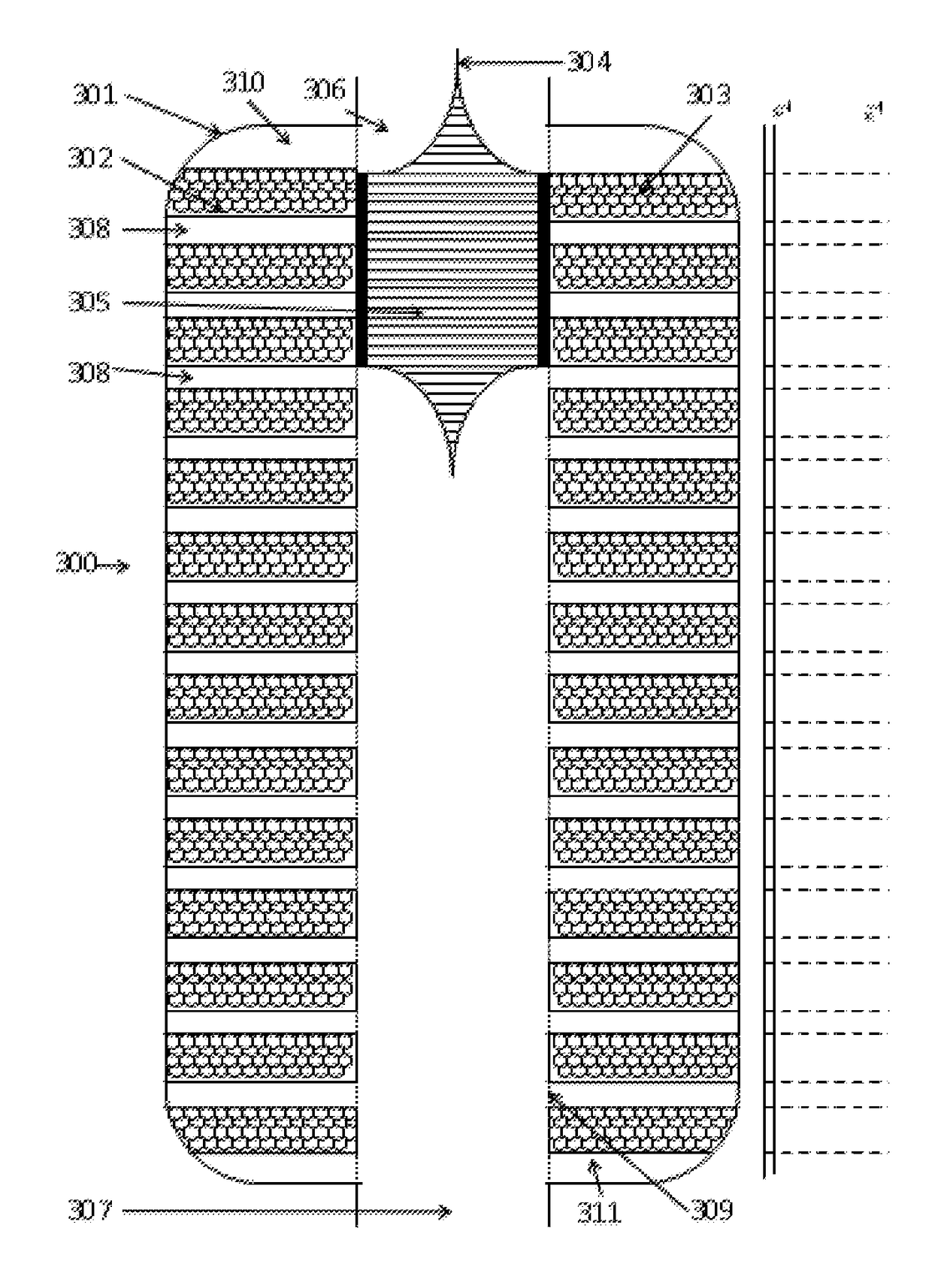
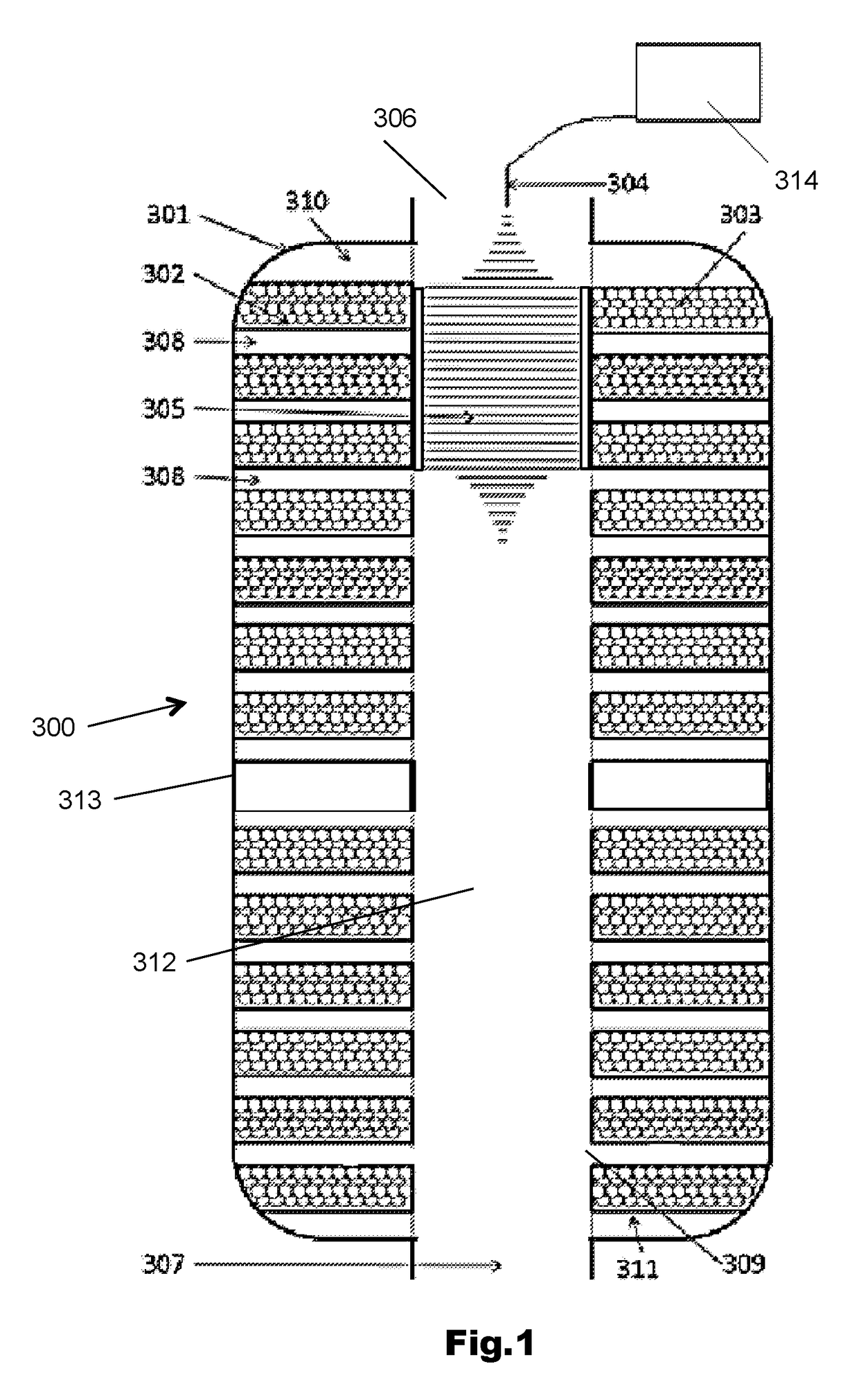
[0068]FIG. 1 is a schematic sectional view of a thermal store 300 according to the present invention. The store 300 comprises a thermally insulated upright chamber or pressure vessel 301 and thermal media 303 arranged in layers on a thermal media support structure 302. The thermal media 303 is in the form of a porous or particulate solid, such as for example, gravel. Gas inlet / outlets 306 and 307 are provided at each end of the chamber and communicate directly with a central cylindrical main flow passageway 312 formed by a cylinder 309 which extends vertically through the chamber alongside the storage media 303 through the respective layers.

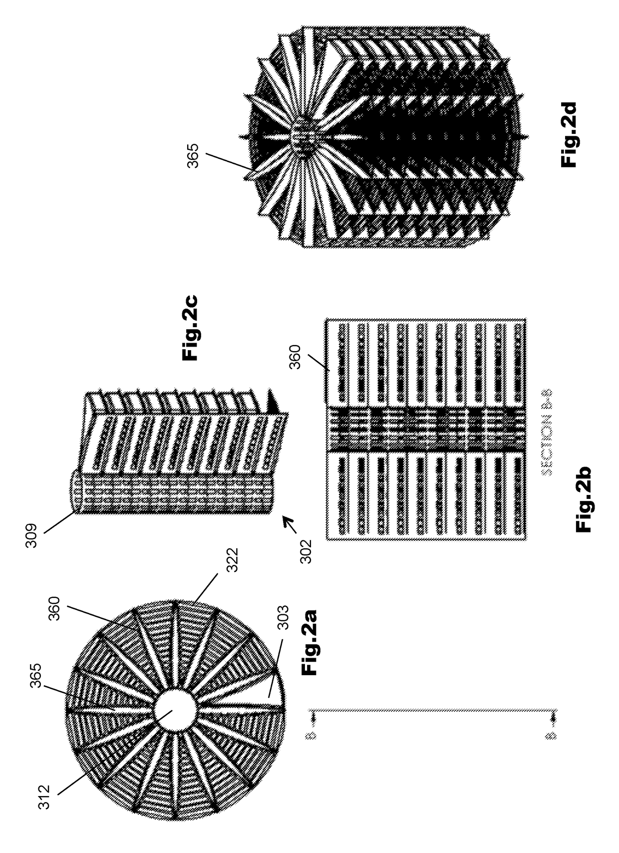
[0069]Referring to FIGS. 2 and 3, these show the support structures 302 and supporting cylinder 309 of the layered store 300 in more detail. The system is modular and comprises a cylinder 309 which acts as a support for the remaining support structure 302. The support cylinder 309 has multiple rows of apertures 350, which are arranged at interval...


PUM


Abstract

Heat storage apparatus comprising at least one thermal store (300) comprising a chamber (301) having a gas inlet (306), a gas outlet (307), and a gas-permeable thermal storage media (303) disposed therebetween, the apparatus being configured such that, during operation, the flow path of a gas flowing through the chamber (301) from inlet (306) to outlet (307) for transfer of thermal energy to or from the storage media (303) can be selectively altered in response to the progress of the thermal transfer, thereby enabling the flow path to bypass inactive upstream or downstream regions of the storage media where thermal transfer is complete or minimal, so as to minimize the pressure drop across the storage media. A baffle system (305) in a main flow passageway (312) may be used to control the gas flow path.

Description

RELATED APPLICATION DATA[0001]This U.S. national phase application is based on international application no. PCT / GB2011 / 051595, filed on Aug. 24, 2011, which claimed priority to British national patent application no. 1104867.5, filed on Mar. 23, 2011. Priority benefit of these earlier filed applications is hereby claimed.FIELD[0002]The present invention relates to apparatus for storing thermal energy, and a method of operating the same. The apparatus may form part of apparatus for receiving and returning energy in the form of electricity (hereinafter referred to as “electricity storage” apparatus).BACKGROUND OF THE DISCLOSURE[0003]A number of systems have been proposed for electricity storage that store the heat of compression of air and absorb the work of expansion of air.[0004]A commonly proposed example of this is called Adiabatic CAES where a salt cavern is typically used as a compressed air store. When electricity is to be stored a motor drives a compressor to compress air int...

Claims


Application Information

Patent Timeline
Patent Type & Authority Patents(United States)
IPC IPC(8): F28F27/00F28F13/06F28D19/00F28D20/00F28F9/22
CPCF28F13/06F28D19/00F28D20/0056F28D2020/006F28D2020/0013F28D2020/0026F28F2009/226Y02E60/142F24S60/00Y02E10/40Y02E60/14H02J15/00F28D2020/0082F28D2020/0069F28D17/00
Inventor HOWES, JONATHAN SEBASTIANMACNAGHTEN, JAMESHUNT, ROWLAND GEOFFREY
Owner ENERGY TECH INST
Why Eureka
Try Eureka