
Method and apparatus for recovering and transporting methane gas

a technology for methane gas and transportation methods, applied in the field of recovery of methane gas, to achieve the effect of reducing the temperature, facilitating transportation, and not affecting the recovery

Inactive Publication Date: 2007-09-27
COMPRESSED ENERGY SYST LLC
View PDF27 Cites 10 Cited by
  • Summary
  • Abstract
  • Description
  • Claims
  • Application Information

AI Technical Summary

Benefits of technology

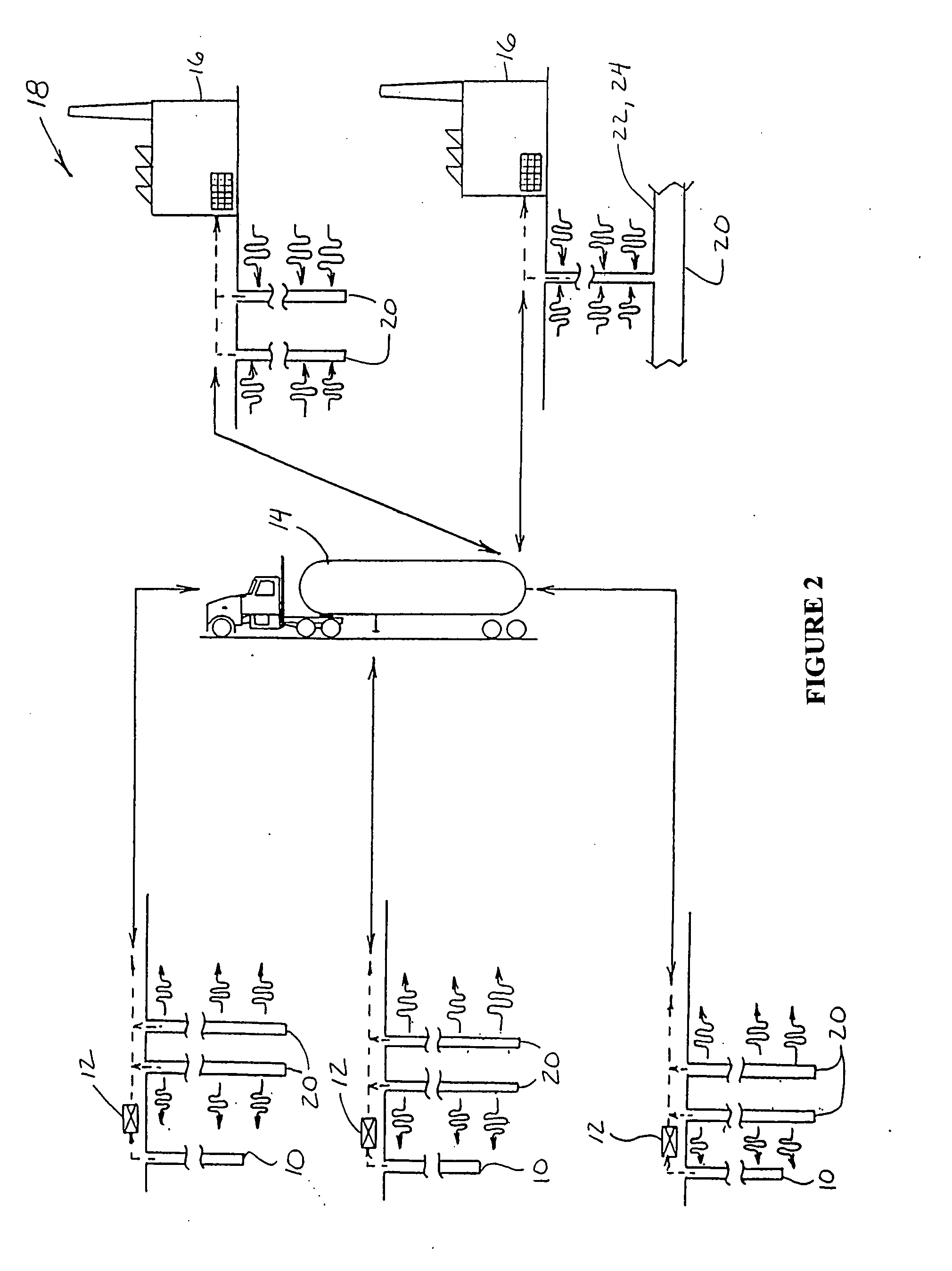
[0023]Another advantage of the invention is keeping the gas at an elevated temperature during loading of a transport from the capacitor, which is done by discharging the gas capacitor. When 3000 psi is discharged initially into the empty transport at 0 psi, the pressure drop is tremendous as is the velocity of the gas flow. This creates a freezing action, such that the temperature of the gas will typically drop 1 degree Fahrenheit for every 15 psi drop in pressure. This will typically drop the temperature 200 degrees over the course of the unloading. This can cause the regulators to freeze even if they are insulated. Gas will also liquefy at 220 degrees below zero, which is also desired to be prevented. The gas stored in a capacitor, because the capacitor is insulating, will retain much of its heat from compression, over time, so as to still be at an elevated temperature when transferred to a tanker. As a result, when loading from one or more capacitors into an initially low pressure tanker, the temperature drop will be from an elevated temperature, much higher than, for instance, the ambient air temperature, such that a freezing action can be avoided. The main problem associated with freezing is that the gas is well-head gas that has not yet been processed. The gas capacitor is in the field to facilitate transportation from the well head to be processed. Without processing, the gas will contain moisture, which has to be removed during processing. This moisture will cause problems if the gas temperatures are well below zero degrees during loading. The geothermal capability of the gas capacitor of the invention will reduce this problem, because the cooling of the gas can be retarded or slowed by the insulating nature of the earth or the formation surrounding the capacitor or capacitors, so as not to drop in temperature as drastically. This will also facilitate unloading due to the warmer gas from the loading, as even after being transported for several hours, for instance, 1 to 2 hours, the gas in the tanker will still be warmer at unloading.
[0024]As the gas is unloaded from the capacitor from a pressure of, for example, 3000 psi and loaded into a transport tanker, the gas again will get very cold. This temperature can cause freezing problems before the gas gets to the processing plant. Using a number of wells (or subterranean cylinders) as capacitors at the unloading site, for instance, three wells (or a formation, an unused or abandoned coal mine, or one or more subterranean cylinders), the geothermal action of the normalized temperature of the subterranean surroundings of the capacitor, for instance, about 58 degrees Fahrenheit, will advantageously warm up the gas.
[0025]Also, utilizing a well or subterranean cylinder in connection with a geological formation such as sand rock as a gas capacitor will allow the gas to load into the formation while holding pressure in the capacitor. The pressure holding saves pressure from the compression that was generated at the well sites which will eliminate need for a compressor at the unloading site. This pressure can then be used to deliver the gas out of the gas capacitor to the gas processing plant or end user. The gas pressure can be controlled with a pressure reducing regulator from the gas capacitor to the processing plant instead of a compressor. It is anticipated that the formation portion of the capacitor will be able to take several tanker loads of gas before a portion of the gas is to be removed from the capacitor. This provides a cushion in the system which will drive the gas and / or save the pressure during discharging as long as the amount of gas discharged during for instance a 24 hour period is the same that is loaded into the capacitor during the same 24 hour period.

Problems solved by technology

Unused or abandoned oil wells are a liability for plugging if not operated.
Many companies are willing to give them away due to plugging costs up to $5,000 per well.

Method used


Image

  • Method and apparatus for recovering and transporting methane gas
  • Method and apparatus for recovering and transporting methane gas
  • Method and apparatus for recovering and transporting methane gas

Examples


Embodiment Construction

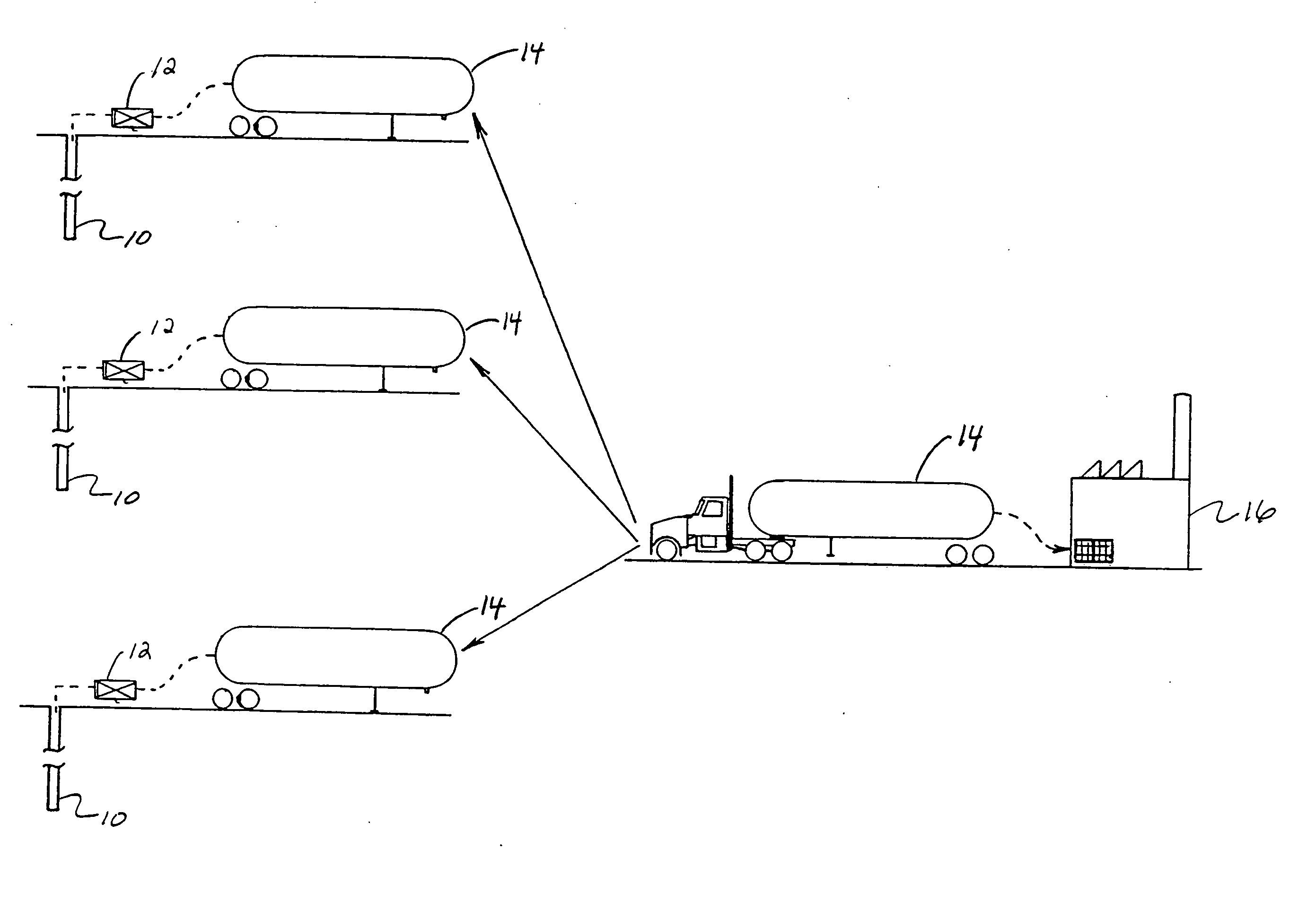
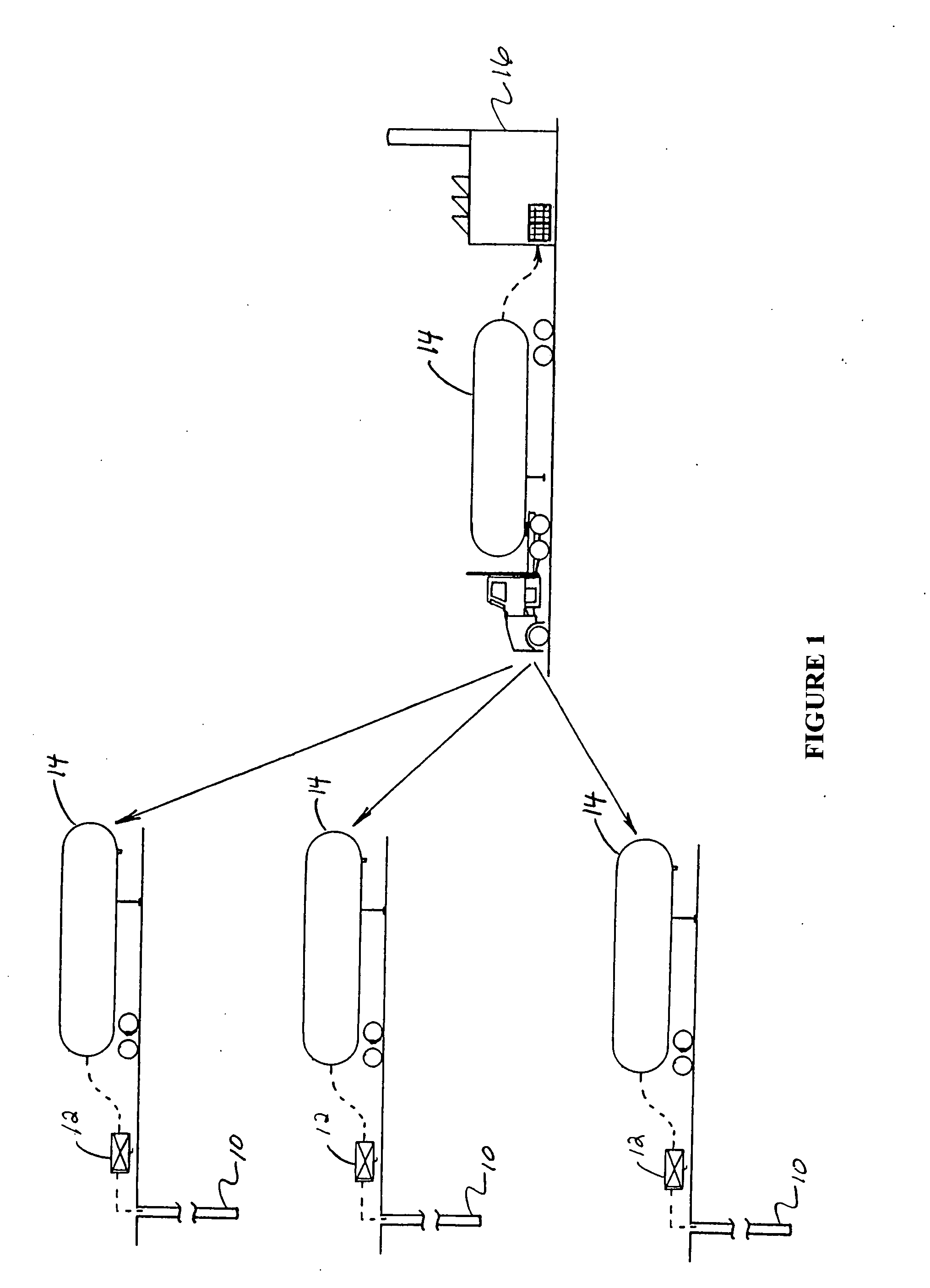
[0029]Referring now to the drawings, wherein like numerals refer to like parts, FIG. 1 illustrates well-known prior art apparatus and methods for recovering and transporting methane gas from a source, such as one or more gas wells in association with one or more underlying coal mines, and transporting the methane gas to an end user, such as, but not limited to, a power generation facility, pipeline, or the like. Essentially, at one or more gas wells 10, conventional, well known apparatus for recovering methane gas therefrom will typically include a compressor 12 in connection with the well 10 using a suitable pipe network (shown by the dotted lines) for receiving or drawing methane gas from a well 10 and compressing the gas into a suitable transport tanker 14. Such tankers 14 are also of conventional, well known construction and operation and can typically hold gas compressed to up to about 3000 psi. At the typical rate at which the methane gas can be extracted and compressed, it wi...


PUM


Abstract

This invention relates to the field of the recovery of methane gas from a coal mine and conventional Natural Gas. More particularly, it involves an apparatus and method for economically recovering methane gas from a coal mine and transporting the methane gas to an end user or other location. The invention further provides an apparatus and method for economically recovering Natural Gas that is stranded due to high impurities that requires processing and / or Natural Gas that is not located near a pipeline. According to a first preferred embodiment of the invention, such methods for recovering and transporting gas comprise (a) transferring gas from a producing well to a first subterranean capacitor and storing the gas in said capacitor and (b) transferring gas from the first subterranean capacitor to a second subterranean capacitor, a pipeline, an end user, a gas processor, or a power plant.

Description

CROSS-REFERENCE TO RELATED APPLICATIONS[0001]This application claims priority to, and incorporates by reference, U.S. provisional patent application Ser. No. 60 / 1784,412, filed Mar. 21, 2006.FIELD OF THE INVENTION[0002]This invention relates to the field of the recovery of methane gas from a coal mine and conventional Natural Gas. More particularly, it involves an apparatus and method for economically recovering methane gas from a coal mine and transporting the methane gas to an end user or other location. The invention further provides an apparatus and method for economically recovering Natural Gas that is stranded due to high impurities that requires processing and / or Natural Gas that is not located near a pipeline.BACKGROUND OF THE INVENTION[0003]As coal is mined, a large amount of methane gas accumulates in the mine. Sometimes this methane gas is simply vented to the atmosphere or burned off. At other times, it is allowed to accumulate.[0004]Much attention has recently been focu...

Claims


Application Information

Patent Timeline
Patent Type & Authority Applications(United States)
IPC IPC(8): E21B43/00
CPCE21B43/00F17C2270/0581F17C5/06F17C7/00F17C2201/0109F17C2201/035F17C2201/052F17C2203/0604F17C2203/0619F17C2203/0639F17C2203/0678F17C2205/013F17C2205/0338F17C2221/033F17C2223/0123F17C2223/036F17C2223/045F17C2225/0123F17C2225/036F17C2227/01F17C2227/0135F17C2227/0157F17C2227/0302F17C2227/046F17C2227/048F17C2260/025F17C2260/048F17C2265/061F17C2270/0149E21B43/006
Inventor SCHIMP, CHRISTOPHER E.
Owner COMPRESSED ENERGY SYST LLC
Learn More